
User Manual

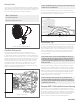
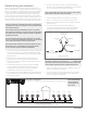
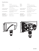

Figure 4: SLS Wiring Diagram
Conguration: 4 SATs:1 SUB or up to 8 SATs:1 SUB
Figure 3: Connect
7. After all the speaker connections are completed, connect the
wires to your amplier. See Figure 4.
8. Turn your amplier on and test the system with your favorite
music. If the speakers are operating properly, rell the wire
trench and enjoy your new system.
Satellite Wiring and Installation
Sonance Landscape Series systems allow for speakers to be
daisy chained together. In a typical system with one zone of audio,
simply run a stereo or 4 conductor speaker wire from the amplier
to the closest speaker. Designate the rst speaker as either left
or right and connect the appropriate positive and negative wires
to the speaker terminals. Continue alternating the wires between
the left and right channels for each speaker, creating a daisy chain
of stereo satellites. The Subwoofer can be wired anywhere in the
chain and will receive either left or right speaker wires. See Figure 4.
Twist wires
together
Waterproof
Wire Nuts
To next
speaker/subwoofer
To
Amplifier
Positive
+
Negative
-
Expandable
Sonamp DSP 2-750 Amplifier
LS4T SATs & LS12T SUB/LS15T SUB or LS6T SATs & LS12T SUB/LS15T SUB
LeftLeft RightRight LeftLeft RightRight
S/N
CAUTION
RISK OF ELECTRIC SHOCK
DO NOT OPEN
AVIS
RISQUE DE CHOC ELECTRIQUE
NE PAS OUVRIR
AC 100-120V ~ 60Hz
AC 220-240V ~ 50Hz
IR
CONTROL
TCP/IP
D
EFAULT IP
1
92.168.1.50
IR
STATUS
IN
OUT
CAUTION
REPLACE FUSE ONLY WITH SAME
T
YPE AND RATING OF FUSE
A
TTENTION
REMPLACER UNIQUEMENT AVEC
LE MEME TYPE ET CALIBRE DU
FUSIBLE
T10AL / 250VAC
DSP2-750 MKII
+
1- LEFT
1- RIGHT
-
BRIDGE
4OHMSMIN
VOLTAGE TRIGGER
IN OUT
+
- -
+
3-30 volts AC /DC
IN
OUT
IN
OUT
1-L 1-R 2-L 2-R
+
-
+
-
2. Once the accessories have been mounted at the desired
locations, mount the satellites by threading the mounting shaft
into the corresponding opening of the accessory.
2
NOTE: DO NOT STAKE SLS SPEAKERS WITHIN DIRECT SPRAY RANGE OF
SPRINKLER HEADS. KEEP AT A DISTANCE OF 2 FEET OR GREATER FROM
DIRECT WATER STREAMS.
NOTE: SONANCE STRONGLY RECOMMENDS THE USE OF 14/4 DIRECT
BURIAL WIRE FOR DISTANCES UP TO 200 FEET AND 12/4 DIRECT BURIAL
FOR LONGER RUNS. KEEP WIRES AS SHORT AS POSSIBLE TO MINIMIZE
RESISTIVE WIRE LOSSES.
CAUTION: THE AMPLIFIER SHOULD NOT BE CONNECTED TO AC POWER
UNTIL ALL SPEAKER WIRE CONNECTIONS ARE COMPLETED. HIGH POWER
70 VOLT AMPLIFIERS PRESENT A SERIOUS SHOCK HAZARD.
NOTE: BEFORE INSTALLING SATELLITE SPEAKERS, ENSURE THAT EACH
ONE HAS BEEN SET TO THE APPROPRIATE 70V/100V OR 8 OHM TAP
SETTING FOR YOUR SYSTEM DESIGN AND REQUIREMENTS.
1. Once Locations have been established, choose the appropriate
mounting accessories for the project. PLEASE NOTE: Always
use a #3 Phillips head screwdriver when ne tuning the height
adjustment screw.
• For applications on at surfaces, such as the side of a
building or structure, use the SM1 Round Surface Mount.
See instruction manual included with accessory for precise
mounting instructions.
• For placement directly into the ground, use the GS9 ABS
in-ground stake for the LS4T SAT, and/or the GP19 PVC
Ground Post for the LS6T SAT. See Instruction Manual
included with accessory for precise instructions.
• For in-tree Mounting, use the TSMJB Tree / Surface Mounting
Junction Box. See Instruction Manual included with accessory
for precise instructions.
NOTE: ATTENTION MUST BE PAID TO THE ELECTRICAL LEADS TO AVOID
NICKS AND CUTS THAT MIGHT SHORT THE SYSTEM.
3. Prepare individual leads to be connected to main leads.
4. Dig a 4” – 5” deep trench for running the speaker wires.
5. Run the wire through the trench from the amplier to the rst
speaker location.
6. Connect the direct burial wire to each speaker wire;
connections should be made with either silicone lled wire
connectors or appropriate junction boxes. See Figure 3.
IMPORTANT: BE SURE NOT TO LET ANY STRAY ‘+’ & ‘–’ STRANDS TOUCH
EACH OTHER. TOUCHING STRANDS CAN CAUSE A SHORT-CIRCUIT THAT
COULD DAMAGE YOUR AMPLIFIER AND DEGRADE SOUND QUALITY.
NOTE: THE SUBWOOFER
CAN BE CONNECTED
AT ANY POINT IN THE
DAISY CHAIN.