
User's Manual

FCC ID: WUO-770102
IC: 7985A-770102
Page 3 of 4
SONAVOX Inc.
Wireless Audio Transceiver Module - 770102
Users Manual
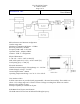
All supply pins should have decoupling electrolytic capacitors and ferrite beads positioned as
close to the supply pins as possible.
All digital audio pins must have small resistors (10..20 Ohms) or ferrite beads in series and
positioned close to the module.
No components or traces should be located close to the antenna. Recommended minimum
distance is 1sm.
Communications
External devices can communicate with and through the module using low speed serial interface
such as single wire communications (such as Infra Red Remote Control protocol) or systems
using multiple connections (such as I2C, UART, SPI).
Audio devices (ADC, DAC) have dedicated high speed digital audio serial bus that can be
configured as (Left Justified, I2S or Right Justified). The configuration can be up to 24bit audio
data with sampling rates of up to 48kHz. Audio Latency is selectable from 6ms to 25.1ms
Addressing
Several systems can work in close proximity when they have different address. The address is
randomly generated during paring mode. The pairing mode is typically started using an external,
user accessible switch connected to one of the GPIO pins of the module.
Firmware
Sonavox can provide customized firmware on the module for our customers.
Other features
The module is RoHS compliant.
The module is FCC approved (documentation available on request).
The module is IC approved (documentation available on request).
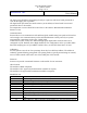
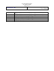
Module Pin-out
Pin Number
Description
1
BCK – Digital audio – Bit clock
2
LRCLK – Digital Audio – Left/Right Clock
3
SDATA – Digital Audio - Data
4
MCLK – Digital audio – System Clock
5,7,9,20
GND
6
RF_TxRx_Vcc (+3.3V)
8
Control_Vcc (+3.3V)
10
RF_PA_CTRL_Vcc (+3.3V)
11
TDI/O_GPIO[1] – Micro-controller programming pin / General Purpose IO
pin
12
TDI_GPIO[2] - Micro-controller programming pin / General Purpose IO pin