
User manual


7 Equipment
109
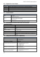
maximum measured conductor diameter: 20 mm
clamp lead length: 1.5 m
operating temperature: –10C…+55C
humidity: 85% RH
height: 2000 m
electromagnetic compatibility: IEC 61000-6-3:2008
IEC 61000-6-2:2008
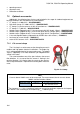
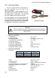
7.2.4 C-7 current clamp
C-7 Clamps are used to measure alternating currents in net-
works of low and medium power within the range up to 100 A.
The output signal is a voltage proportional to the measured current
at the sensitivity of 5 mV/A. It is introduced via a cable (length: 1.5
m) ended with a plug suitable for a socket in the meter.
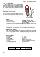
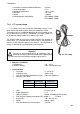
The arrow marked on one of the clamps indicates the direction of
current flow. It is assumed that the current flows in the positive di-
rection if it flows from the source to the receiver. This orientation of
clamps is required for the correct power measurement.
Attention!
Do not use non-insulated clamps for conductors with a
potential exceeding 300 V with respect to the ground and
in systems with the measurement category higher than III.
Reference conditions
temperature: +18…+28°C
relative humidity: <85% (non-condensing)
Technical data
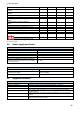
test range 0…100 A AC
frequency range 40 Hz..3 kHz
maximum allowable continuous current 100 A AC (50/60 Hz)
accuracy (sine wave)
Frequency
Basic
uncertainty
Phase error
45…65 Hz
±0,5% ±0.1 mV
2
40 Hz…1 kHz
±1.0% ±0.2mV
unspecified
ratio: 5mV AC/1 A AC
output impedance 11
type of insulation: double, according to IEC 61010-1
measurement category according to IEC 61010-1: III 300 V,
dimensions: 100 × 60 × 26 mm
weight: approx. 160 g
maximum diameter of tested cable: 24 mm
Fig. 47. C-7 clamp.