
User manual


PQM-702, PQM-703 Operating Manual
12
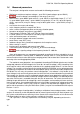
1.6 Measured parameters
The analyzer is designed to measure and record the following parameters:
RMS phase and phase-to-phase voltages - up to 760 V (peak voltages up to ±1500 V),
transient voltages (overvoltages) in the range up to ±6 kV,
RMS currents: up to 3000 A (peak currents - up to ±10 kA) using flexible clamps (F-1, F-2, F-
3); up to 1000 A (peak values - up to ±3600 A) using clamps (C-4 or C-5); up to 10 A (peak
values - up to ±36 A) using C-6 clamps, or up to 100 A (peak values - up to ±360 A) using C-7
clamps,
crest factors for current and voltage,
mains frequency within the range of 40..70 Hz,
active, reactive and apparent power and energy, distortion power,
harmonics of voltages and currents (up to 50th),
Total Harmonic Distortion THD
F
and THD
R
for current and voltage,
K-Factor (factor loss in transformers caused by higher harmonics),
active and reactive powers of harmonics,
the angles between voltage and current harmonics,
power factor, cosφ (DPF), tanφ,
unbalance factors and symmetrical components for three-phase mains,
flicker severity P
st
and P
lt
,
interharmonics of voltages and currents (up to 50th),
Total Interharmonic Distortion TID
F
and TID
R
for current and voltage,
mains signaling voltage in the frequency band of 5...3000 Hz.
Some of the parameters are aggregated (averaged) according to the time selected by the user
and may be stored on a memory card. In addition to average value, it is also possible to record
minimum and maximum values during the averaging period, and to record the instantaneous value
occurring at the end of aggregation period.
The module for event detection is also expanded. According to EN 50160, typical events include
voltage dip (reduction of RMS voltage to less than 90% of nominal voltage), swell (exceeding 110%
of the nominal value) and interruption (reduction of the supplied voltage below 5 % of the nominal
voltage) The user does not have to enter the settings defined in EN 50160, as the software provides
an automatic configuration of the device to obtain power quality measurement mode compliant with
EN 50160 The user may also perform manual configuration - the software is fully flexible in this
area. Voltage is only one of many parameters for which the limits of event detection may be defined.
For example, the analyzer may be configured to detect power factor drop below a defined value,
THD exceeding another threshold, and the 9th voltage harmonic exceeding a user-defined percent-
age value. Each event is recorded along with the time of occurrence. For events that relate to ex-
ceeding the pre-defined limits for voltage dip, swell, interruption, and exceeding minimum and max-
imum current values, the recorded information may also include a waveform for voltage and current.
It is possible to record 5 mains cycles of up to 1 second, with adjustable pre-triggering time. To-
gether with the waveform, half-cycle RMS values (RMS
1/2
) may be also recorded with time adjusta-
ble from 1 s to 5 s.
A very wide range of configurations, including a multitude of measured parameters make the
analyzer an extremely useful and powerful tool for measuring and analyzing all kinds of power sup-
ply systems and interferences occurring in them. Some of the unique features of this device make
it distinguishable from other similar analyzers available in the market.
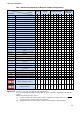
Tab. 1 presents a summary of parameters measured by analyzer, depending on the mains
type.