
User manual
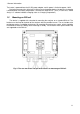


1 General Information
13
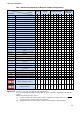
Tab. 1. Measured parameters for different network configurations.
Network type,
channel
Parameter
1-phase
2-phase
3-phase wye with N,
3-phase delta
3-phase wye
without N,
L1
N
L1
L2
N
TOT
L1
L2
L3
N
TOT
L12
L23
L31
TOT
U
RMS voltage
U
DC
DC voltage
I
RMS current
I
DC
DC current
F
Frequency
CF U
Voltage crest factor
CF I
Current crest factor
P
Active power
Q
1
, Q
B
Reactive power
(1)
D, S
N
Distortion power
S
Apparent power
PF
Power Factor
Cosφ/DPF
Displacement power factor
tanφ
tangent φ factor
(1)
THD U
Voltage total harmonic distortion
THD I
Current total harmonic distortion
K
K-Factor
E
P+
, E
P-
Active energy (consumed and sup-
plied)
E
Q1+
, E
Q1-
E
QB+
, E
QB-
Reactive energy (consumed and
supplied)
(1)
E
S
Apparent energy
U
h1
..U
h50
Voltage harmonic amplitudes
I
h1
..I
h50
Current harmonic amplitudes
φ
UI1
.. φ
UI50
Angles between voltage and current
harmonics
P
h1
..P
h50
harmonics active power
Q
h1
..Q
h50
harmonics reactive power
Unbalance U, I
Symmetrical components and unbal-
ance factors
P
st
, P
lt
Flicker
TID U
Voltage total interharmonic distortion
TID I
Current total interharmonic distortion
U
ih0
..U
ih50
Voltage interharmonics amplitudes
I
ih0
..I
ih50
Current interharmonics amplitudes
UR1, UR2
Mains signalling in voltage
U
t
Voltage transients
(2)
Explanations: L1, L2, L3 (L12, L23, L31) indicate subsequent phases
N is a measurement for voltage channel N-PE or current channel I
N
, depending on the parame-
ter type,
TOT is the total value for the system.
(1) In 3-wire networks, the total reactive power is calculated as inactive power
(see discussion on reactive power in section 5.3)
(2) Voltage transients are measured in channels: L1-PE, PE-L2, L3-PE and N-PE.