
User manual

2 Operation of the analyzer
25
according to the
"Power and har-
monics" profile
1 s
3-phase
wye
(1000 events)
(1000 events)
22.5 day
all possible pa-
rameters
10 min
3-phase
wye
4 years
all possible pa-
rameters
10 s
3-phase
wye
25 days
all possible pa-
rameters
10 s
1-phase
64 days
all possible pa-
rameters
10 s
1-phase
(1000 events
/ day)
(1000 events /
day)
14.5 days
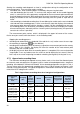
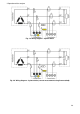
2.8 Measuring circuits
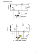
The analyzer may be connected directly and indirectly to the following types of networks:
1-phase (Fig. 15)
2-phase (split-phase) with split-winding of the transformer (Fig. 16),
3-phase 4-wire wye with a neutral conductor (Fig. 17),
3-phase 3-wire wye without neutral conductor (Fig. 18),
3-phase delta (Fig. 19).
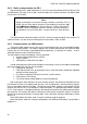
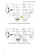
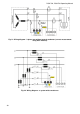
In three-wire systems, current may be measured by the Aron method, which uses only two
clamps that measure linear currents I
L1
and I
L3
. I
L2
current is then calculated using the following
formula:
This method can be used in delta systems (Fig. 20) and wye systems without a neutral conduc-
tor (Fig. 21).
In systems with neutral conductor, the user may additionally activate current measurement in
this conductor, after installing additional clamps in I
N
channel. This measurement is performed after
activating in settings the option of N-conductor current with option Measured.
An alternative to I
N
current measurement with clamps is the calculation of current in neutral conduc-
tor applying the analytical method. The analyzer provides such option after selecting N-conductor
current and Calculated. Neutral current is calculated from the following relations:
, in a single-phase system,
, in a 2-phase system,
, in a 3-phase 4-wire wye system.
These relations stated above are true provided that zero current is present in PE conductor. In
typical situations, this current is indeed negligible, but note that in emergency situations (e.g. short
circuit - until the switch breaker is tripped) current in PE conductor may reach significant values;
therefore the calculated value of current I
N
will differ from the actual.
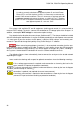
Note
As the voltage measuring channels in the analyzer are referenced to N
input, then in systems where the neutral is not present, it is necessary to
connect N input to L3 network terminal. In such systems, it is not required
to connect L3 input of the analyzer to the tested network. It is shown in
Fig. 18, Fig. 19, Fig. 20 and Fig. 21 (three-wire systems of wye and delta
type).