
User manual

PQM-702, PQM-703 Operating Manual
26
Note
In order to correctly calculate total apparent power S
e
and total Power
Factor (PF) in a 4-wire 3-phase system, it is necessary to measure the
current in the neutral conductor. Then it is necessary to activate option N-
conductor current and connect 4 clamps, as shown in Fig. 17. Another
option is to turn on analytical calculation of current I
N
. More information on
total apparent power S
e
- see sec. 5.3.5.
For systems with available PE and N conductors (earthing and neutral) it is also possible to
measure N-PE voltage. To do this, connect PE conductor to PE voltage input of the analyzer. In
addition, select option N-PE voltage in measurement point settings.
Pay attention to the direction of current clamps (flexible and CT). The clamps should be installed
with the indicating the load direction. It may be verified by conducting an active power measurement
- in most types of passive receivers active power is positive. When clamps are incorrectly con-
nected, it is possible to change their polarity using "Sonel Analysis 2" software.
When measuring overvoltages (transients) is also required, remember that the ana-
lyzer measures them in relation to PE input. Therefore, in such always ensure that PE input of the
analyzer is connected to a local earthing. This remark applies to all types of systems, including 3-
wire systems. Unconnected PE conductor will result in a failure to detect transients.
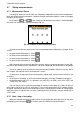
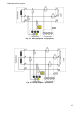
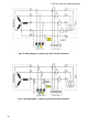
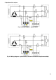
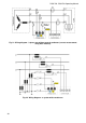
The following figures show schematically how to connect the analyzer to the tested network
depending on its type.
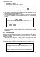
Icons used in the drawings with respect for optional connections have the following meanings:
if U
N-PE
voltage measurement is required, make connection as shown by the icon in dia-
gram (connect PE input to the protective conductor)
if I
N
current measurement is required, make connection as shown by the icon in diagram
(connect clamps in channel I
N
).
connection is optional (not required for correct measurement).
if transients measurement is required, make connection as shown by the icon in diagram
(connect PE input to the local earthing or protective conductor)