
User manual

2 Operation of the analyzer
31
Note
Frequency response of transformers is usually very narrow, so the net-
work disturbances at high frequencies (e.g. lightning surges) are largely
suppressed and distorted on the secondary side of the transformer. This
should be taken into account when making transient measurements in
configuration with transformers.
2.9 Example of use
The procedure presented below shows how to make a sample measurement with the analyzer
('step by step'): from connecting the device to generating the measurement report. It provides
guidelines how to quickly start to operate the analyzer and Sonel Analysis 2 software. It is assumed
that Sonel Analysis 2 software is already installed. The example assumes the use of PQM-703
analyzer. For PQM-702 skip recording of transients, as this measurement is not available in this
analyzer.
Scenario: single-phase measurement acc. to user settings.
Measurement scenario is as follows: the user wants to measure voltage parameters of 1-phase
network 230 V 50 Hz. The measurement is to be made with averaging equal to 1 second. The
following parameters are to be recorded:
average values of voltage, THD and harmonics,
frequency,
voltage event detection should be turned on and set at level of: 105% U
nom
for swell, 95%
U
nom
for dip, 10%U
nom
for interruption. When an event is detected, the waveform and RMS
1/2
graph must be recorded.
transients should be activated at the lowest possible voltage threshold of 50 V (the most
sensitive setting) and a sampling frequency of 10 MHz. Transient graph recording should
be activated.
After the measurement, generate timeplots of measured parameters and a sample
measurement report. Data should be saved for further analysis.
How to perform the measurements:
Step 1: Connect the analyzer to the tested network, as shown in Fig. 15. Connect inputs L1, N, and
PE (for transient measurements). Clamps do not need to be connected, as the current measurement
is not required. Power supply of analyzer (red wires) may be also connected to the tested network
to avoid battery discharge during recording.
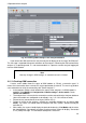
Step 2: Turn on the analyzer by pressing button. Screen 1/9 should be displayed as shown
in Fig. 5.
Step 3: run "Sonel Analysis 2" program. Connect the analyzer to a PC via USB cable. If this is the
first connection, wait to install the drivers of the analyzer.
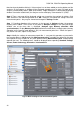
Step 4: click "Settings" on the toolbar of Sonel Analysis 2 or select AnalyzerSettings from the
menu. Then in the displayed window click "Receive". This will result in reading the current
configuration of the measurement points saved in the analyzer.
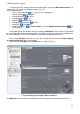
Step 5 (optional): If the analyzer has not been previously connected to the program (status at the
bottom bar of Sonel Analysis 2 indicates "Disconnected" in red, when the analyzer is not connected
to the program), then clicking "Receive" will result in displaying window for connecting with the
analyzer. This window should display one analyzer found (if not, click "Search again"). Select the