
User manual

PQM-702, PQM-703 Operating Manual
32
found analyzer by double-clicking it. If the analyzer has not been added yet to the database of the
analyzers in the program, a window will be displayed prompting user to enter PIN code of the
analyzer. Default factory code is "000" (three zeroes). Proper connection is confirmed by displaying
window "Connection established" (the analyzer screen will display "Connected to PC (USB)".
Step 6: Then a message will be displayed asking user to confirm the read-out of settings. Click
"OK" and then in the confirming window also "OK". Doing this will upload the settings of all four
measurement points - they may be viewed and changed in Settings window.
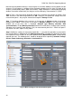
Step 7: Checking allocation of the memory. In the top part of Settings window, the program
displays panel "Local". The first item in this panel is Analyzer settings. In the main part of the
window, one of the three tabs is displayed (Analyzer type, Memory allocation, GPS
synchronization). Display Memory allocation tab and ensure that there is enough space (memory
allocation) on the memory card (default is 25%) for measurement point No. 1. When the space is
very little or set at 0%, adjust it using sliders.
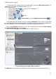
Step 8: Modify the settings of measurement point No. 1 - carry out this operation as presented in
the scenario above. In Local panel click: Measurement point 1, to modify the settings for this point
and expand the tree of cards for this point (double-clicking Measurement point 1 automatically
expands the tree). The following items should be displayed after expanding: Standard, Voltage,
Current, Power and energy, Harmonics, Interharmonics.
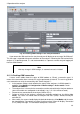
Fig. 23. Main settings of the measurement point.