
User manual
2 Operation of the analyzer
35
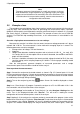
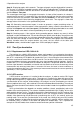
Step 14: Displaying graphs with harmonics. Two types of graphs may be displayed for harmonics.
The first one is a graph of recorded harmonics during the recording period. To display the graph,
first select the time column and then the columns of selected harmonics (e.g. third and fifth order)
and click Plots Time plot.
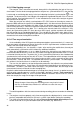
The second type of the graph is a bar graph of harmonics. It shows all the harmonics in selected 1-
second interval (one row). To generate it, first select the desired cell from the time column and then
select the column of any harmonic, click Plots and choose Harmonics. In the same manner, the
user may also select the time interval by dragging time column cells. Then a graph is shown with
average values of harmonics in the specified time period.
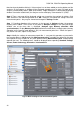
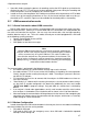
Step 15: Generating measurement report. In order to generate a report containing values of
required parameters, select the columns of these parameters (always select the time column first),
and then click Reports and select User report. Click Preview in the displayed window to see saved
data. Save button saves data in a format specified by the user (pdf, html, txt, csv).
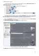
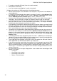
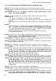
Step 16: Checking events. If the analyzer, during recording process, detects any event, it will be
displayed in a table in Events view. The row describing the specific event displays time of the event
(start and end), extreme value (e.g. minimum voltage during the dip), waveform and RMS
1/2
graph
when the event was voltage- or current-related. In this scenario, event graphs were activated in
settings, therefore when the analyzer detects any event, the last column of the table (with
Waveform header) should include a graph icon. Click it to display the graphs.
2.10 Time Synchronization
2.10.1 Requirements of IEC 61000-4-30
The analyzer has a built-in GPS receiver, whose main purpose is to synchronize the analyzer
clock with an atomic clock signal distributed via GPS satellites. Time synchronization of the analyzer
with UTC is required by IEC 61000-4-30 standard for Class A for marking the measurement data.
Maximum error cannot exceed 20 ms for 50 Hz and 16.7 ms for 60 Hz. Such action is necessary to
ensure that different analyzers connected to the same signal provide identical read-outs. Synchro-
nization with UTC is also needed when the network of analyzers is dispersed. When the source of
the time signal becomes unavailable, an internal real-time clock has to ensure the accuracy of time
measurement with accuracy better than ±1 second to 24 hours, but even in these conditions, to
ensure the compliance with class A, the accuracy of measurement must be the same as previously
specified (i.e., max. 1 period of mains).
2.10.2 GPS receiver
A GPS receiver and antenna is installed inside the analyzer, in order to receive GPS signal
outdoors without any additional accessories. The antenna is installed in the lower left corner of the
casing under the top cover (in a place where GPS logo on the sticker is applied). To enable the time
synchronization of the analyzer inside buildings, the analyzer must be connected to an external
antenna (optional accessory), with a cable of 10 m and installed outside of the building. The analyzer
detects the external antenna and switches into the receiver mode instead of using additional internal
antenna.
GPS synchronization time depends on weather conditions (clouds, precipitation) and on the
location of the receiving antenna. The antenna should be provided with high "visibility" of the sky in
order to obtain the best results. To read the time with the required accuracy, the GPS receiver must
first determine its own current geographical location (it must "see" at least 4 satellites - position and
altitude). After determining the position and synchronizing time to UTC, the receiver enters the
tracking mode. To ensure time synchronization in this mode, the visibility of only one GPS satellite
is required. However, to determine the analyzer position (when it is moved), still four satellites must
be available [seen] (3 satellites if GPS does not update the altitude data). This is important for
example in anti-theft mode, when the device needs continuous position information.