
User manual

5 Power quality - a guide
83
where: u
0
– unbalance factor for zero sequence,
u
2
– negative sequence unbalance,
U
0
– zero symmetric component,
U
1
– positive sequence symmetrical component,
U
2
– negative sequence symmetrical component.
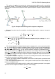
The most convenient method to calculate the symmetrical components and unbalance is using
the complex number calculus. The vectors parameters are amplitude of the voltage (current) fun-
damental component and its absolute phase shift angle. Both of these values are obtained from
FFT.
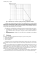
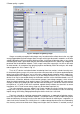
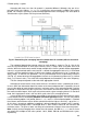
5.8 Voltage dips, swells and interruptions
Voltage dips, swells and interruptions are network disturbances when the effective voltage
(RMS) is significantly different from the nominal value. Each of the three states may be detected by
the analyzer when the event detection is activated and when the user defines the threshold values.
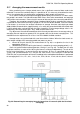
Voltage dip is a state during which the RMS voltage is lower than the user-defined voltage dip
threshold. The basis for the dip measurement is U
RMS(1/2)
, which is the one period RMS value re-
freshed every half period.
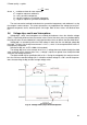
Definition of dip (acc. to IEC 61000-4-30 standard):
The voltage dip starts at the moment when U
RMS(1/2)
voltage decreases below the dip threshold
value, and ends at the moment when U
RMS(1/2)
voltage is equal to or greater than the dip threshold
value plus the voltage hysteresis.
The dip threshold may be specified at 90% of U
nom
. During the voltage dip, the analyzer remem-
bers the minimum recorded voltage (this is called the residual voltage U
res
and is one of the param-
eters characterizing the dip) and the average voltage value.
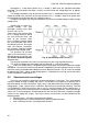
Fig. 35. Voltage swells, dips and interruptions