
User manual

PQM-702, PQM-703 Operating Manual
86
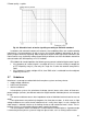
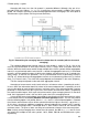
does not exceed the double value of peak voltage in standard conditions), and then the disturbance
is suppressed in oscillatory way. The oscillating nature of the disturbance is caused by the interac-
tion of the capacitor capacitance with network inductance and resulting resonance. The oscillation
frequency is usually around a few hundred Hz. The resistance in the circuit results in gradual sup-
pression of these oscillations. The whole transient usually lasts no longer than a few - few dozen
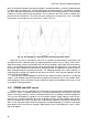
milliseconds. An example of such a transient is shown in Fig. 38.
Fig. 38. An example of a transient after switching capacitor banks.
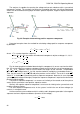
Apart from the causes listed above, transients in networks are generated by switching on and
off capacitive loads, inductive loads, by tripping protection devices (fuses) and by short-circuits.
Switching on loads (circuits) connected to the transformer windings, often leads to ferroresonance,
which is an oscillating transient caused by resonance between the capacitances in the circuit and
by the non-linear inductance of transformer ferromagnetic core. Disconnection of inductive loads is
often accompanied by the sparking on contacts. The voltage generated at the switch contacts ex-
ceeds boundary voltage of the dielectric and spark-over occurs, which may be repeated, until the
gap is too big for breakdown.
Transients may also be propagated in different ways between network segments, e.g. lightning
stroke in a MV network can partially penetrate through the transformer to a LV sub-network. Atten-
uation properties of the transformer usually significantly reduce the amplitude of the surge, as well
as change its timing parameters.
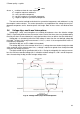
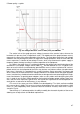
5.10 CBEMA and ANSI curves
CBEMA curve was first proposed in the 70's of the last century by the organization that gave
the curve its name - Computer and Business Equipment Manufacturers Association (now Infor-
mation Technology Industry), which associated manufacturers of computer and office equipment.
The curve was developed as a guide in the construction of power supply adapters and at the be-
ginning it was a graph showing the tolerance of equipment to the size and duration of the disturb-
ances in the power grid. Later, the curve was used to design equipment sensitive to voltage fluctu-
ations as the reference range in which the equipment must operate properly. Finally the curve began
to be widely used in the analyses of power-supply quality in terms of disturbances such as swells,
dips, interruptions.