User’s Manual for the Boundary Devices Neon board R December 28, 2005 December 28, 2005 Revision 2.
1 Revision History Date 2005-03-20 2005-04-03 2005-06-11 2005-06-27 2005-07-23 2005-08-09 2005-09-15 2005-10-21 2005-11-07 2005-11-09 Revision 1.0 1.3 2.0 2.1 2.2 2.3 2.4 2.5 2.6 2.7 2005-12-28 2.
CONTENTS 3 Contents 1 Revision History 2 2 Intended Audience 5 3 Overview of features 5 4 Hardware feature 4.1 Layout . . . . . . . . . . 4.2 Mounting . . . . . . . . 4.3 Connector reference . . 4.4 Electrical characteristics 5 5 6 6 8 . . . . . . . . . . . . . . . . . . . . . . . . . . . . . . . . . . . . . . . . . . . . . . . . . . . . . . . . . . . . . . . . . . . . . . . . . . . . . . . . . . . . 5 Software features 5.1 Das U-Boot . . . . . . . . . . . . . . . . . . . . .
CONTENTS 4 . . . . . . . . . . . . . . . . . . . . . . . . . . . . . . . . . . . . . . . . . . . . . . . . . . . . . . . . . . . . 30 30 30 32 33 7 Configuration Notes 7.1 Display configuration . . . . . . . . . . . . 7.1.1 What display is currently selected? 7.1.2 What displays are supported...? . . 7.1.3 Select a supported display . . . . . 7.1.4 Define and test a new display . . . 7.1.5 Saving settings to Flash EEPROM 7.2 Memory size configuration . . . . . . . . . 7.3 Upgrading U-Boot . .
2 Intended Audience This document aims to provide the information needed to integrate the Neon R board into your application. As such, it addresses both hardware and software integration. 3 Overview of features The following are highlights of the Neon R board.
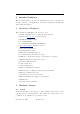
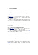
4.2 Mounting 6 Figure 1: Neon board 4.2 Mounting The Neon R board measures 2.75” by 6.75”, slightly larger than the Hitachi R 6.2” display, to allow for easy mounting. There are four mounting holes 1/4” from each edge in each of the four corners, and the holes are 1/8” in diameter. 4.3 Connector reference The following is a list of all connector part numbers used on the Neon R platform for use in identifying mating parts for your application.
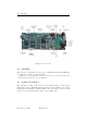
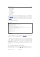
December 28, 2005 Figure 2: Connector Pin-outs Revision 2.8 J4 J1 J19 1 1 J16 + 3.3 VOLTS A B THE DOT ON EACH CONNECTOR DESIGNATE PIN 1 NOTE PIN 10 PIN 8 GPIO 0 ON CPU UNBUFFERED (ONLY 3.3 VOLT TOLERANT PIN 7 GPIO 0 ON CPU UNBUFFERED (ONLY 3.3 VOLT TOLERANT PIN 5 GPIO 3 ON CPU UNBUFFERED (ONLY 3.
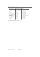
4.4 Electrical characteristics Description USB Master USB Slave I2C Ethernet Stereo Audio Backlight inverter MMC/SD TFT Display Touch Screen Serial Port JTAG 4.4 8 Manufacturer FCI SINGATRON FCI Halo Singatron Molex AVX Part 87520-0010B KS-001-BNW 68897-001 HFJ11-2450E 2SJ-43723N13 53048-0210 14 5638 009 511 862 Molex FCI Molex 52207-0590 68897-001 53048-0810 Electrical characteristics December 28, 2005 Revision 2.
5 Software features As provided by Boundary Devices, the Neon R board supports either Windows CE 5 R or Linux. To simplify the installation of either, the Das U-Bootboot loader is installed on our evaluation boards, and two MMC cards are shipped to allow the use of either operating system. 5.1 Das U-Boot The Das U-Boot Boot Loader is a full-featured loader for either Linux or Windows CE that supports a wide variety of options for loading your Operating System and application.
5.1 Das U-Boot 10 Base/diffutils Devel/binutils Devel/gcc Devel/make Devel/patchutils Utils/bzip2 Web/wget The second requirement for building is the X-Scale cross-compiler itself. The GNUARM project provides a wealth of information needed to build a cross-compiler for ARM processors. Thankfully, it also provides an installer. As of this writing, Boundary Devices currently uses the GCC-3.4.3 package for Cygwin. 5.1.3 General build steps Quick start: wget http://easynews.dl.sourceforge.
5.1 Das U-Boot 11 your application. In general, the file u-boot-1.1.2/include/configs/neon.h defines these choices. In particular, the distributed copy currently expects a Windows BMP file named bdlogo.bmp to be present on the MMC card and writes it to the display, then loads an operating system image from a file named nk.nb0 to RAM address 0xa0030000 and executes it. Both of these are defined by the lines which resemble this: #define CONFIG_BOOTCOMMAND "mmcinit; " \ "fatload mmc 0 a0000000 init.
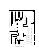
5.1 Das U-Boot 5.1.5 12 U-Boot Memory layout The following diagram shows the general layout of RAM within Das U-Boot. 0xA4000000 0xA3FF8000 0xA3FF7FFF 0xA2000000 0xA1FFFFFF 32K segment used for page tables.
5.1 Das U-Boot 5.1.6 13 U-Boot Init Script The Das U-Boot boot loader comes with scripting facilities in the form of the Hush parser and the autoscript command. You should notice when first compiling the package that the Boundary Devices sample uses this to defer most board initialization to the MMC card. It does this by setting the CONFIG BOOTCOMMAND environment variable as follows. #define CONFIG_BOOTCOMMAND "mmcinit; fatload mmc 0 a0000000 init.
5.2 Windows CE 5.2 14 Windows CE As mentioned earlier, the Neon R board ships with a runnable Windows CE 5.0 image on MMC card. A Board Support Package is also available and necessary to tailor the operating system for a given application. The following sections describe the process of producing an image matching the one shipped with the Neon R board. 5.2.
5.2 Windows CE 5.2.3 15 Building the demo The Platform Builder project used to construct our sample image may be found on the Boundary Devices web site. After installation of the BSP, this project may be copied to a new directory within the WINCE500 PBWorkspaces directory and built using Platform Builder. C:\WINCE500\PBWorkspaces>md bdWeb C:\WINCE500\PBWorkspaces>cd bdWeb C:\WINCE500\PBWorkspaces\bdWeb>wget http://boundarydevices.com/bdWeb.pbxml --17:37:40-- http://boundarydevices.com/bdWeb.
5.3 Linux Support 5.3 16 Linux Support The Linux Environment for Boundary Devices boards consists of four primary pieces, a toolchain, the kernel and device drivers, a user-space build tool based on PTXDist and a Javascript runtime used to demostrate the capabilities of the hardware. 5.3.1 Crosstool Linux Toolchain Before the kernel and applications can be built, it is first necessary to have a cross-compiler toolchain. The following examples show how we at Boundary Devices set up our toolchains.
5.3 Linux Support 17 Note that this will take a looong time2 . Find something else to do while you wait. When complete, you should find a whole slew of programs in your /opt/crosstool/gcc-3.4.3-glibc-2.3.5/arm-xscale-linux-gnu/bin/ directory: -rwxr-xr-x -rwxr-xr-x -rwxr-xr-x -rwxr-xr-x -rwxr-xr-x -rwxr-xr-x -rwxr-xr-x -rwxr-xr-x -rwxr-xr-x -rwxr-xr-x -rwxr-xr-x -rwxr-xr-x -rwxr-xr-x -rwxr-xr-x -rwxr-xr-x -rwxr-xr-x -rwxr-xr-x -rwxr-xr-x -rwxr-xr-x -rwxr-xr-x -rwxr-xr-x -rwxr-xr-x 5.3.
5.3 Linux Support 18 GCC_DIR=gcc-3.4.3 GCC_EXTRA_CONFIG= Then, create a shell script named following content. crosstool-0.37/contrib/newlib/arm-elf.sh with the #!/bin/sh set -ex TARBALLS_DIR=/armArchives RESULT_TOP=/opt/crosstool export TARBALLS_DIR RESULT_TOP GCC_LANGUAGES="c,c++" export GCC_LANGUAGES # You should do the mkdir before running this, # and chown /opt/crosstool to yourself so you # don’t need to run as root. mkdir -p $RESULT_TOP # Build the toolchain.
5.3 Linux Support 5.3.4 19 Kernel 2.4.19 Arm-Linux kernel version 2.4.19 PXA Patches Boundary Devices patches 5.3.5 Linux kernel patches for ARM processors Intel PXA support for ARM-Linux Boundary Devices support Kernel 2.6 wget http://www.kernel.org/pub/linux/kernel/v2.6/linux-2.6.11.11.tar.bz2 bzcat linux-2.6.11.11.tar.bz2 | tar xvf wget http://boundarydevices.com/boundary-2.6.11.11-2005-11-17.patch.bz2 cd linux-2.6.11.11 bzcat ../boundary-2.6.11.11-2005-11-25.patch.
5.3 Linux Support 5.3.6 20 Userland build tool As mentioned before, we at Boundary Devices use a variant of an older version of the PTXDist tool to keep track of the cross-compilation needs for various libraries. This allows inter-library dependencies to be expressed, and also allows the canonical source locations to be used during a build. This should really be better documented, but the short and simple build instructions are as follows. $ $ $ $ wget http://boundarydevices.com/userland_20051126.tar.
5.3 Linux Support 21 the components may take a while, it is often useful to perform this step by itself after configuration. The get makefile target can be used to perform this step. Note that the original web locations are generally used for each library supported by the userland build. This is generally a good thing, but also means that things sometimes move. We try to keep a set of archives on the Boundary Devices website for use when the original sources are unavailable.
5.3 Linux Support 5.3.7 22 Userland libraries and applications The following libraries and applications are included in the userland build.
5.3 Linux Support 5.3.8 23 Notes about userland root filesystems Section 5.3.6 refers to the cramfs target without really indicating its’ use. The cramfs option is one of three primary ’bundled’ targets: 1. cramfs - Creates a single file as a read-only, gzip-compressed image of a filesystem tree. When you can nail down the content of your filesystem, this is a great choice, providing the fastest boot time (around 7 seconds on a PXA-255) and complete immunity to corruption.
5.3 Linux Support 24 Linux boot command line parameters to the kernel also helps here. Typical usage includes is of the following form, which supplies both the MTD partition information and the root filesystem reference: mtdparts=phys_mapped_flash:1024k(armboot),256k(params),-(rootfs1) root=/dev/mtdblock3 rootfstype=cramfs In English, this reads as something like: MTD partitions are 1MB (named armboot), 256K(named params), with the remainder of flash named rootfs1.
5.3 Linux Support 5.3.9 25 mmcinitrd.u-boot The mmcinitrd.u-boot userland Makefile target has a lot of parts, but its’ goal is simple Provide an application developer a means of staying focused on development without the possibility of trashing a flash. It presumes the existence of an SD card formatted with the VFAT filesystem, and a cramfs image on the SD card (in the root as cramfs.img). The mmcinitrd.
6 6.1 Development Tools minidebug minidebug is a small (under 16k) debugger designed to fit completely within the instruction cache on the PXA-255 processor to allow testing of boards even in the absence of ROM or RAM. It also includes features to download over either serial or Ethernet, allows the display and manupulation of registers and memory, and supports controlled execution through breakpoints and data watchpoints. Upon entry, minidebug generally displays a dot (.
6.2 JTAG system-level debugger 6.1.1 27 mdebug The mdebug image adds Ethernet and wireless download capabilities using the Blast protocol to the Neon R . The SSID and DLW commands above are only valid when mdebug is present. The following is an example of the use of mdebug and DLW. Note that the first commands used download mdebug to address A1C00000 and run it from there. Also note that the use of DLW requires a DHCP or BOOTP server for IP address assignment. DLW example .
6.2 JTAG system-level debugger 28 a new device. That said, we also use it extensively as a terminal emulator during development and have added a number of extensions for that purpose. The current release supports the PXA250, PXA255, PXA270, and SA1100 (lart untested). It checks the IDCODE register and uses the appropriate BSDL structure. 6.2.1 Requirements The jtag executable runs either under Linux or Cygwin. Under Linux, there are no known dependencies except for libc and libstdc++.
6.2 JTAG system-level debugger 29 jtag -i Identify the flash part used This option tries to identify the part number of the Flash EEPROM. Currently supported parts are 28F160F3B, 28F320J3A, 28F128J3A, 28F320C3B, and 28F320S3, though not all have been tested. It should be relatively easy to add new parts. jtag -f Generate the appropriate signals to program a flash. This option is rarely used, since we normally program the flash through the minidebug software.
6.2 JTAG system-level debugger 6.2.3 30 Control Keys Once running, the jtag program responds to a number of command sequences, all beginning with [Ctrl A] . [Ctrl [Ctrl [Ctrl [Ctrl [Ctrl [Ctrl [Ctrl 6.2.4 A] A] A] A] A] A] A] B S L T P Q R Send a break Send a file using XModem Toggle logging to jtag.
6.2 JTAG system-level debugger 31 to receive a file. Use the [Ctrl A] S sequence to instruct jtag to prompt for and send a file using XModem. To abort the operation, either when prompting for a filename or before, use [ctrl-C]. . dl a1f00000 CCCCCCCCCCCCCC enter binary file name: u-boot.bin CCCCCCCCCCCCCCCC............................................ ....................................
6.3 TeraTerm blast extensions 6.3 32 TeraTerm blast extensions As an alternative to the jtag executable, Boundary Devices has also produced an extension to the TeraTerm open-source terminal emulator with support for the Blast R protocol. It has the following benefits over the use of jtag: • Does not require Cygwin and ioperm • Because it’s a Windows R graphical application, it’s a bit simpler to use and has a file-chooser dialog.
6.4 6.4 Using U-Boot Networking 33 Using U-Boot Networking One of the most useful features of the Das U-Boot loader is its’ ability to transfer files across a network. As shown below, the dhcp command is typically used to perform both a BOOTP/DHCP request and transfer a file. $ $ set bootfile nk4.nb0 $ set serverip 192.168.0.26 $ dhcp Using MAC Address 00:50:C2:06:30:8F BOOTP broadcast 1 DHCP client bound to address 192.168.0.14 TFTP from server 192.168.0.26; our IP address is 192.168.0.
7 Configuration Notes 7.1 Display configuration The Neon R supports a variety of LCD panels. The following section describes the process of configuring the board for a known, currently supported display panel as well as a Das U-Boot utility command for testing settings on a new panel. If you know the type of panel at compile time, you can place a selection from the list below in the Das U-Boot configuration file include/configs/neon.h.
7.1 Display configuration field name name pixclock type string number xres yres act high hsync len left margin right margin vsync len upper margin lower margin active crt rotation number number number number number number number number number number number number 35 description used to identify the panel Divisor for the pixel clock. Generally 3 for QVGA, 1 for higher resolution.
7.1 Display configuration 36 $ lcdp -----------------------------------name : crt1024x768 pixclock : 65000000 xres : 1024 yres : 768 act_high : 1 hsync_len : 200 left_margin : 24 right_margin : 161 vsync_len : 6 upper_margin : 3 lower_margin : 29 active : 0 7.1.2 What displays are supported...? The lcdp command followed by a question mark will list the currently supported displays. As shown in the following example, the list is extensive (and extensible, as we’ll show later).
7.
7.1 Display configuration name pixclock xres yres act_high hsync_len left_margin right_margin vsync_len upper_margin lower_margin active $ 7.1.3 : : : : : : : : : : : : 38 crt1024x768 65000000 1024 768 1 200 24 161 6 3 29 0 Select a supported display If you supply a supported panel name on the lcdp command line, the display controller will be reset with the associated parameters.
7.1 Display configuration 39 $ set panel hitachi_wvga $ save Saving Environment to Flash... Un-Protected 1 sectors Erasing Flash... Erased 1 sectors Writing to Flash... done Protected 1 sectors $ reset resetting ... $S00#b3 Reset A0008000 U-Boot 1.1.2 (Jun 10 2005 - 22:31:50) U-Boot code: A1F00000 -> A1F20500 BSS: -> A1F54520 RAM Configuration: Bank #0: a0000000 64 MB Flash: 32 MB panel hitachi_wvga found: 800 x 480 ... 7.1.
7.2 Memory size configuration pixclock xres yres act_high hsync_len left_margin right_margin vsync_len upper_margin lower_margin active : : : : : : : : : : : 40 1694498816 800 600 1 200 24 161 6 4 29 1 As with switching to a known panel, the settings take effect immediately upon completion of the command. This can be a very quick way to add support for a new display before committing it to the supported list. Adding an entry into the lcd panels array in common/lcd panels.
7.3 Upgrading U-Boot 41 Use the PHYS SDRAM 1 SIZE variable in include/configs/neon.h to specify the actual size for your hardware. The Windows CE image supports either, but defaults to 32MB. Set the RAM SIZE 64 MB environment variable in your project to indicate that 64MB should be present. The RAM size set in the boot loader is passed to the Linux kernel. 7.3 Upgrading U-Boot As you might expect, Das U-Boot is stored at offset zero in flash EEPROM (i.e. at address zero).
7.4 7.4 Touch Panel Calibration 42 Touch Panel Calibration Under Linux, the flash sector at address 0x140000 is used to store the touchscreen calibration settings. If you’re using bdScript startup code, the calibration routine will launch upon first boot if not defined. Under Windows CE, the touch screen settings are stored on the MMC card in a file named touch.txt. You’ll need to use the mouse to launch the touch calibration program. December 28, 2005 Revision 2.
7.5 7.5 Ethernet MAC Addresses 43 Ethernet MAC Addresses Normally, Neon boards come with their MAC addresses pre-programmed during assembly and test. This is done by using the U-Boot mac command as shown below. Invoked without an argument, the command will display the current MAC address. Used with a single parameter (MAC address with colons separating each pair of hex digits), the command will allow (re)programming of the MAC address.