
User Manual


• • • • • • • • • • • • • • • • • • • • • • • • • • • • • • • • • • • • • • • • • • • • • • • • • • • • • • • • • • • • • • • • • • • • • • • • • • • • • • • • • • • • • • • • • • • • • • • • • • • • • • • • • • • •
I N S T R U C T I O N M A N U A L • M O D E L G X C / G C P O W E R S U P P LY
14
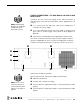
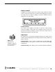
CABLE CONNECTIONS – For GXC Models with 3500 or
4500 Watts Power:
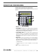
Located at the rear of the power supply are the cable connections as
illustrated below. (The interconnecting cables will be supplied with your
system.)
❶ J1, a round 12 pin RF cable that connects the welding press or converter
to the power supply.
❷ J2, an actuation cable that connects the power supply to a trigger source
(press cable or external trigger source.) Refer to wiring diagrams in
Appendix.
❸ The power line cord that plugs into the appropriate electrical outlet.
Once these connections have been made, the power supply is ready for
operation. If applicable, be sure to consult your welding press instruction
manual to insure that all connections on the press side are correct, and
that the press is ready for operation.
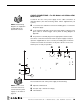
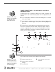
Also located at the rear of the power supply are the following:
NOTE: Detailed wiring
diagrams are supplied in
the Appendix at the
back of this manual.
NOTE: To see a list of
converters that can be
connected to the power
supply, see the table on
the following page.
❷❶
❸
❺
➏
❹❼
❹ Optional J5 External I/O
❺ Fuse (0.5 amp - internal low
voltage)
➏ Circuit breaker
❼ J6 on 1595 only. Press motor
connector.