Redbox User Handbook No3 Mixers & Source Selectors, Microphone Amplifiers, Stereo to Mono Converters, General Interfaces RB-SS10 10 way stereo analogue source selector/mixer RB-DSS10 10 way stereo digital source selector RB-PMX4 10 input, 4 output analogue preset mixer RB-SSML1 Mic/line source selector with compressor/limiter RB-MA1 Microphone amplifier, single RB-MA2 Microphone amplifier, dual RB-DMA2 Dual digital microphone amplifier RB-ML2 Microphone limiter, 2 channel RB-SL2 Twin mono,
Revision 2.07 July 2009 ©Sonifex Ltd, 2000-9 All Rights Reserved Sonifex Ltd, 61, Station Road, Irthlingborough, Northants, NN9 5QE, England. Tel : +44 (0)1933 650 700 Fax : +44 (0)1933 650 726 Email : sales@sonifex.co.uk or technical.support@sonifex.co.uk Web : http://www.sonifex.co.uk Information in this document is subject to change without notice and does not represent a commitment on the part of Sonifex Ltd.
CON TEN TS Warranty i i ii iii Safety Information iii Safety of Mains Operated Equipment Voltage Setting Checks Fuse Rating Power Cable and Connection Ordering the Correct Mains Lead Installation Information Atmosphere Electromagnetic Radiation Fitting Redboxes WEEE & RoHS Directives - Sonifex Statement iii iii iii iv iv iv iv iv iv vi 1 1 RB-SS10 10 Way Stereo Analogue Source Selector/Mixer Introduction System Block Diagram Front Panel Indicators & Controls Illuminated Push Buttons Front Panel Gai
CON T E N TS CO N T E N TS Rear Panel Connections and Operation Outputs 1-4 Front Panel Controls Switch Banks Input Gain Controls Technical Specifications RB-PMX4 22 23 23 23 23 24 4 25 RB-SSML1 Mic/Line Source Selector with Compressor Limiter Introduction System Block Diagram Rear Panel Connections Stereo Monitor Inputs Stereo Monitor Pad & Volume Control Mic Input Mic Input Gain Using Phantom Powered Microphones Using the LF Filter Compression Active on Mic Input Only Peak Hold Disabled on LED Meter
CON TEN TS Mic / Line Inputs Mic Input Gain Using Phantom Powered Microphones Using the LF Filter Mic / Line Outputs Mic / Line Output Gain Level Limiting Mode Select Switch Technical Specifications RB-ML2 46 46 46 46 46 47 47 47 48 8 50 RB-SL2 Twin Mono, or Stereo, Limiter 50 50 51 51 51 51 51 52 9 53 RB-SM1 Single & RB-SM2 Dual Stereo To Mono Converter Introduction System Block Diagram Rear Panel Connections and Operation Stereo Inputs 1 (& 2) Mono Output 1 (& 2) Output Gain Technical Specificati
CON T E N TS CO N T E N TS f Setting the Unit’s Identity Using The Mode ID DIP Switches Setting The Boot Up Mode Force Last Used Studio Mode Force Studio 1 Mode Configuring for Operation Single (MASTER) Mode Studio Connections Control Panels Profanity Delay Connector Mix Input LSO Expansion Port Serial Ports Studio Expansion Studio Connections Control Panels Profanity Delay Connector Mix Input LSO Expansion Serial Ports Bus Expansion Studio Connections Control Panels Profanity Delay Connector Mix Input L
FIGURES Figures Fig A: Packing List. ii Fig B: Mains Cable Wire Colours iv Fig C: Mains Lead Table. iv Fig 4-5: RB-SSML1 Front Panel. Fig D: RB-RK1Small Redbox Front Rack-mount Kit . v Fig E: RB-RK2 Small Redbox Rear Rack-mount Kit. Fig 5-2: RB-MA1 & RB-MA2 Block Diagram Single Channel. 31 v Fig 5-3: RB-MA1 Rear Panel. 32 Fig 5-4: RB-MA2 Rear Panel. 32 Fig 5-5: Switch to Control LF Filter and Phantom Power. 33 Fig 1-2: RB-SS10 System Block Diagram. 2 Fig 6-1: RB-DMA2 Front Panel.
FIGURES FI G U RE S Figures (continued) Fig 11-2: RB-MM1 System Block Diagram. 64 Fig 11-3: RB-MM1 Rear Panel. 65 Fig 12-1: RB-OA3 Front Panel. 68 Fig 12-2: RB-OA3 System Block Diagram. 69 Fig 12-3: RB-OA3 Rear Panel. Fig 12-4: RB-OA3 Unit Identity Definitions. Fig 12-5: RB-OA3 Unit Identity Reset Settings. Fig 12-6: RB-OA3 Studio Expansion Diagram. Fig 12-7: RB-OA3 Bus Expansion Diagram. Fig 12-15: RB-OA3 Transmission I/O Connector Definitions.
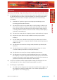
WARR ANT Y Warranty Warranty and Liability - important the purchaser is advised to read this clause (a) The Company agrees to repair or (at its discretion) replace Goods which are found to be defective (fair wear and tear excepted) and which are returned to the Company within 12 months of the date of despatch provided that each of the following are satisfied: Notification of any defect is given to the Company immediately upon its becoming apparent to the Purchaser; (ii) The Goods have only been operated
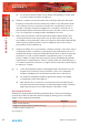
WA R R A N T Y WA RR A N T Y (ii) For any breach by the Company of any statutory undertaking as to title, quiet possession and freedom from encumbrance. (d) Subject to conditions (a) and (c) from the time of despatch of the Goods from the Company’s premises the Purchaser shall be responsible for any defect in the Goods or loss, damage, nuisance or interference whatsoever consequential economic or otherwise or wastage of material resulting from or caused by or to the Goods.
S A FE T Y & INSTALL ATION IN FORMATION Each Redbox is shipped in protective packaging and should be inspected for damage before use. Where an item is found to have transit damage, notify the carrier immediately with all the relevant details of the shipment. Packing materials should be kept for inspection and also for if the product needs to be returned.
S A F E T Y & I N S TA LL AT I ON INF O R MAT I ON Power Cable and Connection SAFE T Y & IN STALL ATION IN FORMAT I ON An IEC power connector is supplied with the Redbox, which has a moulded plug, attached – this is a legal requirement. If no moulded plug has been supplied with your Redbox, please contact your supplier, because an IEC connector is always supplied from the Sonifex factory.
S A FE T Y & INSTALL ATION IN FORMATION They can also be rack-mounted, with either the front, or rear of the Redbox positioned at the front of the rack: Front Mounting Redboxes: For rack mounting smaller (28cm) units the optional RB-RK1 (Red) or RB-RK1B (Black) kit can be used (which include 4 off M6 panel fixing screws). Fig D: RB-RK1Small Redbox Front Rack-mount Kit . Rear Mounting Redboxes: For rear panel mounting you can use either the RB-RK2, or RB-RK3, depending on the size of your Redbox.
S A F E T Y & I N S TA LL AT I ON INF O R MAT I ON WEEE & RoHS Directives - Sonifex Statement SAFE T Y & IN STALL ATION IN FORMAT I ON The Waste Electrical and Electronic Equipment (WEEE) Directive was agreed on 13 February 2003, along with the related Directive 2002/95/EC on Restrictions of the use of certain Hazardous Substances in electrical and electronic equipment (RoHS).
M I X E R & S OURCE SELEC TORS 1 1 RB-SS10 10 Way Stereo Analogue Source Selector/Mixer Introduction Fig 1-1: RB-SS10 Front Panel. As well as being able to act as a source select module, the RB-SS10 can act as a mixer, by enabling the mix mode (using the remote input). The gain for left and right inputs can be individually adjusted by using the preset potentiometers on the front panel.
1 M I X E R & S O URC E S E LE C TO R S System Block Diagram Inputs 1 L R Push Button Switches Mix Mode MIX ER & SO URCE SELEC TORS - RB - S S 1 0 R Front Panel Inhibit 2 Remote Start I/O Remote Start In Audio Inputs L Remote Select/ Switch Inputs Status Outputs MCU Audio Inputs 3-6 Input Gain Stage Outputs Volume x10 L Audio Inputs 7-10 Headphone Outputs R L Analogue Switches Outputs R Fig 1-2: RB-SS10 System Block Diagram.
M I X E R & S OURCE SELEC TORS 1 In mix mode, each button you press will select that source allowing multiple sources to be mixed to a single output. Pressing the button again will switch off a source. There is also a remote input to inhibit the front panel switches. When the front panel inhibit is active, pressing the front panel switches has no effect on the current channel selection.
1 M I X E R & S O URC E S E LE C TO R S INPUT 1 button on = Alternate mode INPUT 2 button on = Latched mode INPUT 3 button on = Protected Alternate mode Rear Panel Connections and Operation MIX ER & SO URCE SELEC TORS - RB - S S 1 0 Master Output Control Outputs Input 1 Additional Audio Input Connects Input 2 Remote Select/ Switch Inputs Status Outputs Remote Start I/O Fig 1-4: RB-SS10 Rear Panel.
M I X E R & S OURCE SELEC TORS 1 RB-SS10 Additional Audio Input Connectors There are 2 off 25 way D-type sockets (female) used for the remaining audio inputs. The INPUTS 3 - 6 (upper) connector contains analogue inputs 3-6, and the INPUTS 7 – 10 (lower) connector contains analogue inputs 7-10. Pin No.
1 M I X E R & S O URC E S E LE C TO R S RB-SS10 Remote Start I/O This 25 way D-type plug (male) connector contains the remote start input connection and the corresponding 10 opto-isolated remote start outputs. This is intended to be used as a method for re-directing a remote start command using a single switch or mixer fader start output, to selected equipment, i.e. CD player, or MD player, etc.
M I X E R & S OURCE SELEC TORS 1 The collector connects to the start pin of the equipment, and the emitter connects to the common pin of the equipment. Start Output Collector 1 to 10 (Pins 1 to 10) Play Command Start Output Emitter 1 to 10 (Pins 14 to 23) Command Common Remote Select/Switch Inputs Remote Inputs 1 to 10 This Front 25 way D-type socket (female) connector contains the front panel inhibit input Panel Inhibit Mix Mode (Pins 1 to 12)the remote switch inputs to control the channel selection.
1 Start Output Collector 1 to 10 (Pins 1 to 10) Play Command Start Output Emitter 1 to 10 (Pins 14 to 23) Command Common M I X E R & S O URC E S E LE C TO R S All of the active low signals have internal pull-ups. Remote Inputs 1 to 10 Front Panel Inhibit Mix Mode (Pins 1 to 12) Signal Ground (Pins 14 to 24) MIX ER & SO URCE SELEC TORS - RB - S S 1 0 Fig 1-9: Connection Example. Status Outputs +5V This(Pins 25 way 14 D-type to 23) socket (female) connector contains the remote status tallies.
Remote Inputs 1 to 10 Front Panel Inhibit Mix Mode (Pins 1 to 12) Signal Ground (Pins 14 to 24) M I X E R & S OURCE SELEC TORS 1 +5V (Pins 14 to 23) Remote Tally 1 to 10 (Pins 1 to 10) Fig 1-11: Connection Example. Audio Specifications Input Impedance: 20kΩ bridging Output Impedance: <50Ω Maximum Input Level: +28dBu Maximum Output Level: +28dBu Frequency Response: 20Hz to 20kHz ±0.1dB (600Ω load, ref 1kHz) Input Gain Range: Adjustable 8dB loss to 20dB gain (L & R adjust).
1 M I X E R & S O URC E S E LE C TO R S Equipment Type RB-SS10: 10 way stereo analogue source selector/mixer MIX ER & SO URCE SELEC TORS - RB - S S 1 0 Physical Specifications 10 Dimensions (Raw): 48cm (W) x 10.8cm (D) x 4.2cm (H) (1U) 19” (W) x 4.3” (D) x 1.7” (H) (1U) Dimensions (Boxed): 53cm (W) x 20.5cm (D) x 6cm (H) 21” (W) x 8” (D) x 2.4” (H) Weight: Nett: Nett: 1.5kg 3.3lbs Gross: Gross: 2.0kg 4.
M I X E R & S OURCE SELEC TORS 2 2 RB-DSS10 10 Way Stereo Digital Source Selector Introduction Fig 2-1: RB-DSS10 Front Panel. The digital receivers in this unit are fully 24 bit, 96kHz capable. When an input is selected from the front panel, or remotely, the unit will attempt to capture the incoming signal on either the AES/EBU or the S/PDIF signal inputs, with priority given to the AES/EBU input.
2 M I X E R & S O URC E S E LE C TO R S System Block Diagram Remote Start I/O Remote Select/ Switch Inputs Push Button Switches Remote Start In M IXER & S OURCE SELEC TORS - RB - D S S 1 0 Inputs AES/ EBU Data Selector MCU Status Outputs Volume Control AES Receiver Outputs Data Selector AES Receiver S/PDIF Data Selector Headphone Output DAC AES Transmitter AES/ EBU S/PDIF Output Fig 2-2: RB-DSS10 System Block Diagram.
M I X E R & S OURCE SELEC TORS 2 Power Indicator The LED on the front panel is used to indicate that power is present on the unit. However, it also has a secondary role to indicate whether the selected channel is routing the AES/EBU or S/PDIF input: Red indicates AES/EBU input. Amber indicates S/PDIF input. The LED and remote tally flash, if the incoming audio signal is not present, to indicate that the incoming digital signal is missing. There is also a remote input to inhibit the front panel switches.
2 M I X E R & S O URC E S E LE C TO R S M IXER & S OURCE SELEC TORS - RB - D S S 1 0 buttons will display the current operating mode (as shown below). To change the mode, simply press the input 10 and the buttons will indicate the newly selected mode. Once the required operating mode has been set the unit will restart within five seconds from the last button press.
M I X E R & S OURCE SELEC TORS 2 Digital Audio Inputs & S/PDIF Output This connector contains the other two remaining professional AES/EBU input connections, and the 10 S/PDIF input connections. It also has the S/PDIF digital output. The S/PDIF digital inputs and the output have an impedance of 75Ω. Pin No.
2 M I X E R & S O URC E S E LE C TO R S Remote Start I/O This 25 way D-type plug (male) connector contains the remote start input connection and the corresponding 10 opto-isolated remote start outputs. M IXER & S OURCE SELEC TORS - RB - D S S 1 0 Pin No.
M I X E R & S OURCE SELEC TORS Start Output Collector 1 to 10 (Pins 1 to 10) Play Command Start Output Emitter 1 to 10 (Pins 14 to 23) Command Common 2 Fig 2-7: Connection Example. Signal Ground Pin(Pins No.
2 M I X E R & S O URC E S E LE C TO R S MIX ER & SO URCE SELEC TORS - RB - S S 1 0 Status Outputs This 25 way D-type socket (female) connector contains the remote status tallies. Pin No.
M I X E R & S OURCE SELEC TORS 2 Technical Specifications RB-DSS10 Audio Specifications 110Ω ±20% balanced (AES/EBU) Input Impedance: 75Ω ±5% unbalanced (S/PDIF) Output Impedance: 110Ω ±20% balanced (AES/EBU) Output Impedance: 75Ω ±5% unbalanced (S/PDIF) Signal Level: 3V/10V peak to peak min/max (AES/EBU) 0.5V ±20% peak to peak (S/PDIF) Sample Freq Range: 30-100kHz (i.e. including 32kHz, 44.1kHz, 48kHz, 64kHz, 88.
2 M I X E R & S O URC E S E LE C TO R S Equipment Type RB-DSS10 10 way stereo digital source selector M IXER & S OURCE SELEC TORS - RB - D S S 1 0 Physical Specifications 20 Dimensions (Raw): 48cm (W) x 10.8cm (D) x 4.2cm (H) (1U) 19” (W) x 4.3” (D) x 1.7” (H) (1U) Dimensions (Boxed): 53cm (W) x 20.5cm (D) x 6cm (H) 21” (W) x 8” (D) x 2.4” (H) Weight: Nett: Nett: 1.6kg 3.5lbs Gross: Gross: 2.2kg 4.
M I X E R & S OURCE SELEC TORS 3 3 RB-PMX4 10 Input, 4 Output Analogue Preset Mixer Introduction Fig 3-1: RB-PMX4 Front Panel . The RB-PMX4 has been designed for situations where a small mixer is needed for installations where it will be configured and then only altered occasionally, or never altered. Uses for this product are numerous including a four bus mini-mixer, a 4 zone mixer for pubs and clubs, a multiple clean-feed generator and a quad stereo to mono converter to name a few.
3 M I X E R & S O URC E S E LE C TO R S System Block Diagram Balanced XLR Input 1 Gain Balanced XLR Input 2 Gain M IXE R & SO URC E SELEC TORS - RB - PMX4 Balanced XLR Input 3 Gain Output 1 Switch Bank Balanced XLR Input 4 Output 2 Switch Bank Gain Balanced XLR Output 1 Balanced XLR Input 5 Balanced XLR Output 2 Gain Balanced XLR Input 6 Gain Balanced XLR Input 7 Gain Balanced XLR Input 8 Gain Output 3 Switch Bank Balanced XLR Input 9 Gain Output 4 Switch Bank Balanced XLR Output 3 Balan
M I X E R & S OURCE SELEC TORS 3 Inputs 1-10 The XLR-3 input sockets can take balanced professional levels, or unbalanced by using the front panel gain controls, and by connecting the non-phase to the signal ground screen. The XLR 3 pin input has the following connections: Pin 1: Screen Pin 2: Phase Pin 3: Non-phase Pin 1: Screen Pin 2: Phase Pin 3: Non-phase Front Panel Controls 1 Switch Banks 2 3 INPUT LEVEL 4 5 6 7 8 9 10 Input Gain Controls Fig 3-4: RB-PMX4 Front Panel Controls.
3 M I X E R & S O URC E S E LE C TO R S Technical Specifications RB-PMX4 M IXE R & SO URC E SELEC TORS - RB - PMX4 Audio Specifications Maximum Input Level: +28dBu Input Impedance: >20kΩ balanced bridging Maximum Output Level: +28dBu Output Impedance: <50Ω Frequency Response: 20Hz to 20kHz ±0.1dBu (600 Ω load, @ 1kHz) Input Gain Range: Adjustable 8dBu loss to 18dBu gain.
M I X E R & S OURCE SELEC TORS 4 4 RB-SSML1 Mic/Line Source Selector with Compressor Limiter Introduction Mic Volume Line Volume LED Metering Threshold Headphone Control Outputs Compression Control Headphone Volume Fig 4-1: RB-SSML1 Front Panel. The RB-SSML1 is a 1U rack-mountable source selector for compressing or limiting an incoming microphone or stereo line signal and mixing this signal with a stereo monitor input, which can then be metered and mixed to two headphone outputs.
4 M I X E R & S O URC E S E LE C TO R S The metering is carried out after the compressor/limiter section and consists of two rows of 12 round LEDs showing levels between -17dB and +11dB. An internal jumper allows the metering to follow either the stereo output, or the headphone monitor outputs and a rear panel DIPswitch can disable the peak hold display. The headphone output volume control is on the front panel. Each headphone output is designed to drive 150 mW into 32Ω to 600Ω stereo headphones.
M I X E R & S OURCE SELEC TORS 4 Stereo Monitor Inputs The 2 x XLR 3 pin sockets used for the monitor input are electronically balanced. They have the following connections: Pin 1: Screen Pin 2: Phase Pin 3: Non-phase Note: The monitor input can not be mixed to the stereo line output, it is only used for headphone monitoring. Mic Input The XLR 3 pin socket used for the microphone is electronically balanced.
4 M I X E R & S O URC E S E LE C TO R S Using the LF Filter This switch provides control for a high pass filter on the mic input with low frequency roll off at 125Hz. The roll-off filter is in circuit when the switch is down (towards the arrow). Compression Active on Mic Input Only With this feature enabled, the compressor/limiter will only operate when the microphone input is selected. This mode becomes active when switch 3 is down (towards the arrow).
M I X E R & S OURCE SELEC TORS 4 Mic & Line Volume Controls The front panel MIC VOLUME reduces the volume to –80dB. The line input channel with the LINE VOLUME control fully up, has a gain of +6dB. Mic/Line Select Switch To select between microphone or stereo line inputs, use the Mic/Line select switch; stereo line is in the up position. Bypass Button The compressor/limiter section of the product can be switched in and out by using the BYPASS button.
4 M I X E R & S O URC E S E LE C TO R S Technical Specifications RB-SSML1 M IXER & S OURCE SELEC TORS - RB - S S ML1 Audio Specifications (Bypass Mode) Maximum Input Level: -10dBu (mic), +28dBu (line), electronically balanced Input Impedance: 20kΩ nominal balanced Maximum Output Level: +28dBu Output Impedance: <50Ω Headphone Output Level: Drives 150mW into 32Ω to 600Ω headphones Low Frequency Roll-Off: 125Hz @ 6dB/octave Gain Range (mic): Adjustable 36dB to 75dB gain (-80dB volume min.
MICROPHONE AMPLIFIERS & LIMITERS 5 5 RB-MA1 Single & RB-MA2 Dual Microphone Amplifiers Introduction Fig 5-1: RB-MA1 & RB-MA2 Front Panel. All connections and controls are on the rear panel. The microphone input is XLR-3 type and is electronically balanced. The input gain can be adjusted individually by a recessed pre-set potentiometer.
5 M I C RO P H O NE AMPLIFIERS & LI M I T E R S Rear Panel Connections and Operation MI CRO PHO NE AMP LIFIER S & LIMITERS - RB - MA 1 & RB - MA 2 Input Gain Control 32 Mic Input Phantom power LF Filter Output Fig 5-3: RB-MA1 Rear Panel. Input Gain Control Mic Input Phantom Power Switch LF Filters Stereo Outputs Fig 5-4: RB-MA2 Rear Panel. Mic Inputs The XLR 3 pin sockets used for the microphone are electronically balanced.
MICROPHONE AMPLIFIERS & LIMITERS On On 1 On 2 3 4 On 1 Channel 1 Low Frequency (LF) Filter 2 Channel 1 Phantom Power 3 Channel 2 Phantom Power (only applies to MA2) 4 Channel 2 Low Frequency 5 Fig 5-5: Switch to Control LF Filter and Phantom Power. Using the LF Filter A switch also provides control for a high pass filter with low frequency roll off at 125Hz. The filter is in when the switch is in the down position (towards the arrow).
5 M I C RO P H O NE AMPLIFIERS & LI M I T E R S Technical Specifications RB-MA1 & RB-MA2 MI CRO PHO NE AMP LIFIER S & LIMITERS - RB - MA 1 & RB - MA 2 Audio Specifications 34 Maximum Input Level: -10dBu Maximum Output Level: +28dBu Input Impedance: 20kΩ nominal balanced Output Impedance: <50Ω Low Frequency Roll-Off: 125Hz @ 6dB/octave Gain Range: Adjustable 36dB to 75dB gain E.I.N: 130dB Distortion: 0.
MICROPHONE AMPLIFIERS & LIMITERS 6 6 RB-DMA2 Dual Digital Microphone Amplifier Introduction Fig 6-1: RB-DMA2 Front Panel. The microphone inputs are XLR-3 type and are electronically balanced. The input gain for each input can be adjusted individually by coarse and fine gain controls on the front panel and each input has a level indicator. Additionally the fine gain control knob can be disabled by internal jumpers.
6 M I C RO P H O NE AMPLIFIERS & LI M I T E R S For the digital output, there is a switch available to define the content of the channel status bits embedded within the digital audio stream. The channel status bits will be forced to Professional Mode for sample rates above 48kHz, as they are not supported by the Consumer Mode. For sample rates of 32kHz, 44.1kHz and 48kHz, the status bits can be either set to Professional or Consumer Mode.
MICROPHONE AMPLIFIERS & LIMITERS 6 Sync & Power Indicator The LED on the front panel is normally red to indicate that power is present on the unit. However, it also has a secondary role to indicate the status of the digital inputs: Fast flashing between red and amber indicates a loss of digital input signal, or that the unit is being calibrated. Input Level Adjustment Front panel potentiometers, coarse and fine, allow for adjustment of the gain of each microphone input.
6 M I C RO P H O NE AMPLIFIERS & LI M I T E R S RB-DMA2 Inputs Mic Inputs The XLR 3 pin sockets used for the microphone inputs are electronically balanced. They have the following connections: MIC ROP HON E AM PLIFIE RS & LIMITERS - RB - D MA 2 Pin 1: Screen Pin 2: Phase Pin 3: Non-phase 38 AES/EBU Sync Input The digital AES/EBU synchronisation input XLR 3 pin socket has an impedance of 110 Ω and the signals meet the IEC 60968 specification.
MICROPHONE AMPLIFIERS & LIMITERS 6 Rear Panel Controls Status Select Switches These switches are used to determine the status or content of the digital output signals. The type of information encoded in the channel status bits of a digital audio signal can be professional or consumer and is determined by switch 1. However at frame rates higher than 48kHz, consumer mode is not available, so professional mode is used and this switch will be ignored.
6 M I C RO P H O NE AMPLIFIERS & LI M I T E R S Digital Sync & Output Select Buttons These buttons are used to switch the digital connection between the AES/EBU XLR connector (button out) and the S/PDIF phono connector (button in) independently for the digital sync input and the digital output. MIC ROP HON E AM PLIFIE RS & LIMITERS - RB - D MA 2 Note: There is no switch to select the Word Clock as a sync input.
MICROPHONE AMPLIFIERS & LIMITERS 6 Frequencies and Sync Modes Rotary Switch Number Mode Sample Frequency (kHz) Master 32 1 Master 44.1 2 Master 48 3 Master 64 4 Master 88.2 5 Master 96 6 Auto 32 7 Auto 44.1 8 Auto 48 9 Auto 64 A Auto 88.2 B Auto 96 C Auto Lock - D Slave - F Calibration - Fig 6-7: RB-DMA2 Frequency and Sync Rotary Switch Selections.
6 M I C RO P H O NE AMPLIFIERS & LI M I T E R S Technical Specifications RB-DMA2 Connections Analogue Mic Inputs: 2 x XLR 3 pin (balanced) Analogue Line Outputs: 2 x XLR 3 pin (balanced) Digital Sync Inputs: 1 x AES/EBU XLR 3 pin female MIC ROP HON E AM PLIFIE RS & LIMITERS - RB - D MA 2 1 x S/PDIF RCA phono 42 1 x TTL BNC female (sync) 50 ohm impedance Digital Outputs: 1 x AES/EBU XLR 3 pin plug 1 x S/PDIF RCA phono socket Mains Input: Filtered IEC, 110-120V, or 220-240V switchable, fused 10W
MICROPHONE AMPLIFIERS & LIMITERS Sync Modes: Master, Slave, Auto, Auto-Lock via rotary switch Digital Input Select: AES/EBU or S/PDIF, via push-switch Channel Status Bits: Set to consumer or professional mode via DIP switch Output Routing: Set dual mono output via dipswitch Led Level: Green ind. -18dBFS, Orange ind. -12dBFS, Red ind. -6dBFS 6 Equipment Type Dual digital microphone amplifier Physical Specifications Dimensions (Raw): 48cm (W) x 10.8cm (D) x 4.2cm (H) (1U) 19” (W) x 4.3” (D) x 1.
7 M I C RO P H O NE AMPLIFIERS & LI M I T E R S 7 RB-ML2 Stereo Microphone & Line Level Limiter Introduction M ICRO PHO NE AMP LIFIERS & LIMITERS - RB - ML2 Fig 7-1: RB-ML2 Front Panel. 44 The RB-ML2 is a stereo microphone and line level limiter. The unit is mainly used where assistance with level control is required, for protection of mixer inputs and to prevent distortion. The RB-ML2 is ideal for news-booths, and the input to PC work stations, it provides an economical level control solution.
MICROPHONE AMPLIFIERS & LIMITERS 7 System Block Diagram Gain Mic/Line Input 1 LF Filter Mic Gain Mic/Line Output Phantom Power (48V) Gain and Limit Control Line LF Filter Mic Gain and Limit Control Phantom Power (48V) Line Limiter Stage Mic/Line Output Gain Fig 7-2: RB-ML2 Block Diagram.
7 M I C RO P H O NE AMPLIFIERS & LI M I T E R S Mic / Line Inputs The XLR 3 pin sockets used for the mic/line inputs are electronically balanced. They have the following connections: M ICRO PHO NE AMP LIFIERS & LIMITERS - RB - ML2 Pin 1: Screen Pin 2: Phase Pin 3: Non-phase Mic Input Gain Recessed pre-set potentiometers allow for adjustment of the gain of the microphone inputs. This provides a gain range of +22dB to +67dB which enables the use of dynamic and powered microphones.
MICROPHONE AMPLIFIERS & LIMITERS 7 Mic / Line Output Gain The output gain is adjustable from -54dB to -24dB when mic is selected and adjustable between -8dB to +22dB for line, with reference to 0dBu line input. The gain is adjusted via two potentiometers on the rear panel of the unit, although it is pre-set in production. Level Limiting Stereo limiting operates by limiting both left and right outputs if either the left and right input needs to be limited.
7 M I C RO P H O NE AMPLIFIERS & LI M I T E R S Technical Specifications RB-ML2 M ICRO PHO NE AMP LIFIERS & LIMITERS - RB - ML2 Audio Specifications 48 Maximum Input Level: -6dBu (mic), +28dBu (line), electronically balanced Input Impedance: >20kΩ balanced bridging Input Gain Range: Adjustable +22dB to +67dB gain (mic) Via 2 x pre-set potentiometers (L&R), 0dB gain (line) Maximum Output Level: -18dBu (mic), +28dBu (line), electronically balanced Output Impedance: 150Ω(mic), <50Ω balanced (line
MICROPHONE AMPLIFIERS & LIMITERS 7 Equipment Type RB-ML2: Stereo microphone & line level limiter Physical Specifications 28cm (W) x 10.8cm (D) x 4.2cm (H) (1U) 11” (W) x 4.3” (D) x 1.7” (H) (1U) Dimensions (Boxed): 36cm (W) x 20.5cm (D) x 6cm (H) 14.2” (W) x 8” (D) x 2.4” (H) Weight RB-ML2: Nett: 0.90kg Gross: 1.
8 M I C RO P H O NE AMPLIFIERS & LI M I T E R S 8 RB-SL2 Twin Mono, or Stereo, Limiter Introduction MICROP HO NE AM PLIFIERS & LIMITE RS - RB - S L2 Fig 8-1: RB-SL2 Front Panel. The RB-SL2 is a stereo, or twin independent mono, VCA limiter for use in news-rooms and other locations where the correct level into recording equipment is required, but not necessarily under the control of an engineer, for example, for overload protection.
MICROPHONE AMPLIFIERS & LIMITERS 8 Rear Panel Connections and Operation Stereo Outputs Stereo/Mono Switch Stereo Input Fig 8-3: RB-SL2 Rear Panel. Outputs The XLR 3 pin plug connectors are electronically balanced and can be wired unbalanced to accept an output from domestic equipment. They have the following connections: Pin 1: Screen Pin 2: Phase Pin 3: Non-phase Inputs The XLR 3 pin sockets are electronically balanced, and can be wired unbalanced to accept an output from domestic equipment.
8 M I C RO P H O NE AMPLIFIERS & LI M I T E R S Technical Specifications RB-SL2 MICROP HO NE AM PLIFIERS & LIMITE RS - RB - S L2 Audio Specifications 52 Maximum Input Level: +28dBu Maximum Output Level: +28dBu Input Impedance: >20kΩ bridging Output Impedance: <50Ω Input Gain: Adjustable -8dBu to +18dBu gain Limit Threshold: Adjustable -8dBu to +28dBu Frequency Response: 20Hz to 20kHz ±0.1dB (600Ω load, ref 1kHz) Noise: -100dB unity gain, ref +8dBu Distortion: 0.
S T E R E O TO MON O CONVERTERS 9 9 RB-SM1 Single & RB-SM2 Dual Stereo To Mono Converter Introduction Fig 9-1: RB-SM1 & RB-SM2 Front Panel. All connections are on the rear panel. The XLR-3 inputs are electronically balanced with an impedance of 20kΩ bridging. These can be wired unbalanced to accept an output from domestic equipment. The XLR-3 line output’s are electronically balanced with an output impedance of <50Ω.
9 S T E R E O TO MO NO CONVE R T E R S Rear Panel Connections and Operation S TER EO TO M ON O CO NVERTERS - RB - SM1 & RB - S M2 Stereo Inputs 54 Output Gain Control Mono Output Fig 9-3: RB-SM1 Rear Panel.. Stereo Inputs Stereo Inputs Mono Output Mono Output Output Gain Control Fig 9-4: RB-SM2 Rear Panel.
S T E R E O TO MON O CONVERTERS 9 Stereo Inputs 1 (& 2) The input’s are a stereo pair consisting of two XLR 3 pin sockets electronically balanced with an impedance of 20kΩ bridging. They can be wired unbalanced to accept an output from domestic equipment.
9 S T E R E O TO MO NO CONVE R T E R S Technical Specifications RB-SM1 & RB-SM2 STEREO TO M O NO CO NVE RTERS - RB - SM1 & RB - S M2 Audio Specifications 56 Maximum Input Level: +28dBu Maximum Output Level: +28dBu Input Impedance: >20kΩ balanced bridging Output Impedance: <50Ω balanced Frequency Response: 20Hz to 20kHz ±0.1dB (600Ω load, ref 1kHz) Gain Range: Adjust 8dB loss to 18dB gain, ref 0dB input on L and R Common Mode Rejection: >66dB typically Distortion: 0.
G E NER AL IN TERFACES 10 10 RB-LC3 3 Way Light/Power Controller Introduction The RB-LC3 is a triple output switching unit for controlling external mains indicators, primarily studio status lights for broadcasting applications, such as On-Air, Mic-Live and Rehearsal/Live lights. Each output can be individually controlled by one of three remote inputs (pulled high, or low), by a telephony input (when ringing, or off-hook or both), or a combination of two inputs (to control two outputs, e.g.
10 G E N E R A L I NT E R FAC E S System Block Diagram Zero Cross-point Switch Mains Output 1 GEN ER AL INTERFACE S - RB - LC3 Zero Cross-point Switch Mains Output 2 Mains Input Remotes Zero Cross-point Switch Settings And Control Mains Output 3 Status Detection & Ring Mute Telephone Line Input Telephone Handset Output Fig 10-2: RB-LC3 Block Diagram.
G E NER AL IN TERFACES 10 Switched Mains Outputs The 3 off IEC connectors provide the switched mains outputs. Each output is rated at 1A and is individually fused. A neon indicator shows when the output is live. The outputs are driven by zero cross-point drivers. When an output is activated, the A.C. voltage level at that output will be equal to the mains input voltage used to power the unit.
10 G E N E R A L I NT E R FAC E S GEN ER AL INTERFACE S - RB - LC3 Configuration Switches The configuration switches are used to set the flash mode for each output separately. The selections allow the outputs to be controlled by a remote input, a telephone call, or a combination of remote inputs, say, for example to control 2 lights such as “Rehearsal” and “Live”, using the Settings in Figure 10-4 to 10-6.
G E NER AL IN TERFACES Off Off On On Output 1 On when Remote 1 asserted and Remote 2 asserted 14 On Off On On Reserved for future assignment 15 Off On On On Latching Mode selection for Output 1 16 On On On On Momentary Mode selection for Output 1 13 10 Fig 10-4: Output 1 Configuration Setting. The available settings for output 2, configured using switches Sw5 to Sw8, are detailed below: 1 Sw6 Sw7 Sw8 Description Off Off Off Off Flash Output 2 when telephone rings.
10 G E N E R A L I NT E R FAC E S The available settings for output 3, configured using switches Sw9 to Sw12, are detailed below: GEN ER AL INTERFACE S - RB - LC3 Setting Sw9 No Sw10 Sw11 Sw12 Description 1 Off Off Off Off Flash Output 3 when telephone rings.
G E NER AL IN TERFACES 10 Technical Specifications RB-LC3 Connections Non-filtered IEC, 110V-240V auto-adjusting, fused, 6W maximum Fuse Rating (Mains Input): Anti-surge fuse 100mA 20 x 5mm (230VAC) Anti-surge fuse 250mA 20 x 5mm (115VAC) Mains Outputs: 3 x Non-filtered IEC plugs, 1A fused Fuse Rating (Mains Outputs): 3 x Anti-surge fuse 1A 20 x 5mm Telephone: 2 x RJ11-4 sockets Control Inputs & Outputs: 15 way D-type plug Inputs: 0V– 5V DC Outputs: Open Collector 20mA sink capability Equipment
11 G E N E R A L I NT E R FAC E S 11 RB-MM1 Mix Minus Generator Introduction GEN ER AL INTERFACE S - RB - MM1 Fig 11-1: RB-MM1 Front Panel. Whenever programming originates from outside of the studio, or if listeners/viewers are calling up a phone-in using telephone hybrids or codecs, mix-minus feeds are required. Most telephone lines incur delays which prohibit off-air monitoring, because the caller, or remote talent, would hear their own voice in delay which is very disconcerting.
G E NER AL IN TERFACES 11 Front Panel Indicator The LED on the front panel is normally red to indicate that power is present on the unit. Rear Panel Connections and Operation From Mixer Main Output Null Adjustment LF FullOutput Band to TBU Bandpass Output Filter Level Switch Adjustment Fig 11-3: RB-MM1 Rear Panel. Stereo Inputs From Mixer Main Output These inputs should contain the main mixer output which will be a feed of the programme plus the audio that you want to remove by the mix-minus unit.
11 G E N E R A L I NT E R FAC E S Band Pass Filter Switch The band pass filter, when in the ON position, is used to limit the audio bandwidth of the output to the TBU between 200Hz and 4kHz. When using the RB-MM1 in full bandwidth equipment, e.g. for ISDN audio codecs, set this switch to the OFF position. GENE R AL IN TERFACE S - RB - MM1 Output to Telephone Balance Unit (TBU) The mono XLR 3 pin output plug connector is electronically balanced with an output impedance of less than 50Ω.
G E NER AL IN TERFACES >60dB Band Pass Filter Range: 200Hz to 4kHz, 12dB/octave LF Null Adjustment: Better than 40dB at 100Hz Mix-Minus Null: Better than 40dB at 1kHz Frequency Response: 20Hz - 22kHz ± 0.1dB Distortion: 0.
12 G E N E R A L I NT E R FAC E S 12 RB-OA3 3 Studio On-Air Switcher Introduction Offer LED GENE R AL IN TERFACE S - RB - OA 3 Dump LED Power On Indicator Delay LED Studio 2 LED Studio 3 LED Studio 1 LED Fig 12-1: RB-OA3 Front Panel. The RB-OA3 is a 1U rack-mount, unity gain on-air switcher, capable of switching three stereo pairs between three studios.
G E NER AL IN TERFACES 12 The RB-OA3 can be expanded to switch between up to 5 studios or up to 6 stereo pairs by connecting a multiple of units together. With the addition of a single unit, expansion in studio mode allows for 2 additional studios to take control of the transmission path and additional equipment. If the expansion is made in bus mode, then three additional stereo channels can be added. In total 4 x RB-OA3 units can be connected together to switch 6 stereo pairs between up to 5 studios.
12 G E N E R A L I NT E R FAC E S Rear Panel Connections and Operation Transmission Output Connector Studio 2 Control Connector Studio 1 Audio Connector GENE R AL IN TERFACE S - RB - OA 3 LSO Expansion Connector Serial Port 1 Serial Port 2 Fuse Studio 1 Control Mix Input Studio 2 Audio Profanity Delay IEC Mains Connector Connector Connector Control Input Mode Select Studio 3 Control Studio 3 Audio Mix Input Switches Connector Connector ON/OFF Switch Fig 12-3: RB-OA3 Rear Panel.
G E NER AL IN TERFACES OFF This will set the unit to Force Last Used Studio mode ON This will set the unit to Force Studio 1 mode 12 Fig 12-5: RB-OA3 Unit Identity Reset Settings. Force Last Used Studio Mode When a studio is selected, the value of that studio is stored in the unit. This is then recalled on boot up so that the last studio to transmit is reconnected.
12 G E N E R A L I NT E R FAC E S LSO Expansion Port Leave disconnected. Studio Expansion Serial Ports Leave these disconnected. DIP Switch Settings Studio Expansion M GEN ER AL INTERFACE S - RB - OA 3 Master Transmission S Fig 12-6: RB-OA3 Studio Expansion Diagram. Connect two units to allow the switching of 3 stereo busses between 5 studios giving the user control over more studios.
G E NER AL IN TERFACES 12 Bus Expansion Bus Expansion DIP Switch Settings Master Transmission M B Connect two units to allow the switching of 6 stereo busses between 3 studios so that the studios can share more peripheral devices. To achieve this configure one unit as the MASTER and one unit as the BUS EXPANSION SLAVE: Studio Connections Connect three studios to the MASTER unit and connect the MASTER TRANSMISSION OUTPUT to your transmission output destination.
12 G E N E R A L I NT E R FAC E S Studio & Bus Expansion Studio & Bus (4 Unit) Expansion DIP Switch Settings DIP Switch Settings GENE R AL IN TERFACE S - RB - OA 3 Master Transmission M S B B&S Fig 12-8: RB-OA3 Studio & Bus Expansion Diagram. Connect two units to allow the switching of 6 stereo busses between 3 studios allowing the studios to share more peripheral devices.
G E NER AL IN TERFACES 12 (available in the RB-OA3C cable pack). For the BUS EXPANSION SLAVE and STUDIO & BUS EXPANSION SLAVE, there is no need to connect the LSO expansion cables since the LSO is not used in bus expansion. Serial Ports RB-OA3 1 RB-OA3 2 RB-OA3 4 RB-OA3 3 Connect the serial ports of the MASTER and all the SLAVE units together using a standard RJ45 network cable. It is recommended that a full ring system is implemented by connecting each unit to two others.
12 G E N E R A L I NT E R FAC E S in. When the unit is operating as a STUDIO EXPANSION SLAVE, if one of the MASTER unit’s studios is routed to the transmission path, STUDIO 1 LED will always be illuminated. If one of SLAVE’S studios is selected, the MASTER unit’s studio indications will all be extinguished. GENE R AL IN TERFACE S - RB - OA 3 CONTROL PANEL LEDS Each of the control panel connectors has the ability to switch on four LEDS.
G E NER AL IN TERFACES 12 control to take transmission back from it. Think of it as a studio which has no Offer and Accept controls of its own, but which can still be put to and from transmission by the other studios. The sustain studio is Studio 3 by default and this cannot be changed. Once the sustain function is activated, the transmission path switches instantly to Studio 3 and is automatically offered back to all studios.
12 G E N E R A L I NT E R FAC E S Transmission Studio OFFER ACCEPT Other Studio OFFER ACCEPT ACCEPT STATE GENE R AL IN TERFACE S - RB - OA 3 Press OFFER to offer control OFFER STATE Press OFFER to take back control Studio 3 Always Transmission Studio OFFER ACCEPT Press ACCEPT to take control Other Studio OFFER ACCEPT SUSTAIN ACTIVE STATE Press OFFER to arm SUSTAIN MODE Press OFFER to arm SUSTAIN MODE SUSTAIN ARMED STATE (IF ANOTHER STUDIO ARMS) Press ACCEPT to take control or press OFFER t
G E NER AL IN TERFACES 12 Rear Panel Connections & Operation LSO Expansion The connector is 9 a pin female D-type and is used to transfer the last studio to offer channel between units, when used in multiple unit mode.
12 G E N E R A L I NT E R FAC E S Mix Input Selection The interface is a 9 pin female D-type and is used to mix a stereo feed into the transmission path by using the MIX INPUT ON/OFF SWITCH, push button (rear panel, located next to the mix input). This could be an emergency announcement system, PC automation playout system, or other audio source.
G E NER AL IN TERFACES 12 Transmission Outputs and Studio 1-3 Audio Connection Details There are three studio interfaces to connect three individual studios to the unit. There is also a transmission interface which carries the main transmission output and 2 balanced stereo connections for interfacing with external units such as hybrids, or codecs, which you may want to share between studios. These are all 25 way female D-Types and they each carry 4 balanced stereo pairs or 8 mono.
12 G E N E R A L I NT E R FAC E S GENE R AL IN TERFACE S - RB - OA 3 Studio 1-3 Audio Connection Details 1 Transmission Left Phase (Input) 3 Transmission Right Non Phase (Input) 4 1st external unit Left Phase (Input/Output) 6 1st external unit Right Non Phase (Input/Output) 7 2nd external unit Left Phase (Input/Output) 9 2nd external unit Right Non Phase (Input/Output) 10 Last Studio to Offer Left Phase (Output) 12 Last Studio to Offer Right Non Phase (Output) 14 Transmission Left Non Ph
G E NER AL IN TERFACES 12 Studio 1-3 Control Port Connection Details Each studio can be controlled externally via the optional RB-OA3R rack control system or, if the studio uses the Sonifex S2 mixer, the S2-MTBS panel which can be connected to the unit via these control ports. Each control panel enables control of the Offer, Accept and Sustain functions as well as Dump and Delay. There is a pin for each function which needs to be pulled low to activate the function.
12 G E N E R A L I NT E R FAC E S GENE R AL IN TERFACE S - RB - OA 3 Profanity Delay Control A profanity delay unit can be attached and controlled to the unit via this interface. The control is achieved using a relay. Each function has an input pin and two possible output pins. The relay can be configured to complete the circuit and route back the input signal either normally open or normally closed, depending on which output pin is used. The interface is 9 pin male D-type.
G E NER AL IN TERFACES 12 Technical Specifications RB-OA3 LSO Path: >20kΩ Output Impedance: <50Ω Gain Range: Unity gain Frequency Response: 20Hz to 20kHz ±0.1dB Common Mode Rejection: < -52dB typically Distortion: 0.01%THD @ 1 kHz Noise: ~ -87dB unity gain, ref +8dBu Mix Audio Transformer Specifications: Common Mode Rejection: < -64dB @ 10kHz Distortion: 0.5% THD ref 17dBu @ 40Hz Bandwidth: ±0.
12 G E N E R A L I NT E R FAC E S RB-OA3R Remote Switch Panel For RB-OA3 Introduction GEN ER AL INTERFACES - RB - OA 3 R Power On Indicator Offer Button Accept Button Dump Button Delay Button Fig 12-23: RB-OA3R Front Panel. The RB-OA3 has been designed for installation in a central technical area with cabling to custom panels, or selection switches, in each studio. If you don’t have any custom switch panels available, you can use an RB-OA3R in each studio.
G E NER AL IN TERFACES 12 The connections are as follows: 15V 2 Offer Switch 3 Offer Lamp 4 Accept Switch 5 Accept Lamp 6 Delay Switch 7 Delay Lamp 8 Dump Switch 9 Dump Lamp 15 Ground Fig 12-26: RB-OA3R Pin Out Definitions. 8 1 15 9 Fig 12-27: RB-OA3R Pin Out Positions. The 15V supply is fed through resistors to the LEDs. When any button is pressed, the switch links Ground to the switch pin of that specific button.
12 G E N E R A L I NT E R FAC E S Technical Specifications RB-OA3R Connections: Studio Control: 1 x 15 way D type plug (male) Equipment Type GENE R AL IN TERFACES - RB - OA 3 R RB-OA3R: 88 Remote switch panel for RB-OA3 Physical Specification Dimensions (Raw): 48cm (W) x 10.8cm (D ) x 4.2cm (H) (1U) 19” (W) x 4.3” (D) x 1.7” (H) (1U) Dimensions (Boxed): 53cm (W) x 20.5cm (D ) x 6cm (H) 21” (W) x 8” (D) x 2.4” (H) Weight: Nett: 1.2kg Gross: 1.8kg Nett: 2.
G E NER AL IN TERFACES 12 RB-OA3C Expansion Unit Cable Kit For RB-OA3 Introduction If you add another RB-OA3 to an existing unit to expand either the number of busses or studios, you need additional cables to connect it which are contained in this kit: 1 x Transmission output expansion cable, 25 pin D-type male to 25 pin D-type male, 30cm lead, wired pin to pin. 1 x RS232 expansion cable, RJ45 to RJ45 standard wiring, 30cm lead. 1 x kit should be used for each expansion RB-OA3 being used.
13 CO N N E C TO R S & C A B LI NG 13 Connectors & Cabling Many of the problems associated with installing and maintaining studio equipment are due to the use of poor cables or faulty connections. It is recommended that, wherever possible, pre-wired cables are purchased from recommended manufacturers. If you need bespoke cables making, please ensure that a qualified engineer carries out the work.
CONNE C TORS & C ABLIN G 13 D-Type Connectors The following diagram shows the connection details for the D-type connectors as viewed from the rear of a Redbox : Pin 1 Male Pin 14 Pin 13 Pin 13 Pin 25 Pin 25 Female Pin 1 Pin 14 Fig 13-4: 25 Way D-Type Connectors. Male Pin 10 Pin 9 Pin 9 Pin 15 Pin 15 Female Pin 1 Pin 10 Fig 13-5: 15 Way D-Type Connectors. Pin 1 Male Pin 6 Pin 5 Pin 5 Pin 9 Pin 9 Fig 13-6: 9 Way D-Type Connectors.
14 G LO SS A RY 14 Glossary G LOS S A RY 1kHz ADSL 92 1000Hz or 1 kilohertz tone of 1kHz is often used for line-up and testing. Asynchronous Digital Subscriber Link - a broadband delivery system over standard telephone lines (between the exchange and the user). AES Audio Engineering Society. AES/EBU Professional digital audio standard covering frame format, connections and interfaces. Interface is usually on XLR sockets and plugs.
GLOSSARY DAT dB (decibel) DLS DSP EBU EIN ENG EON EQ FM FSD 3G Gain GRAM HDLC Hybrid IEC ISDN Redbox User Handbook No 3 G LOS S A RY DCF DDS & DDS-2 DI Digital Audio Tape. A ratio of two voltages or signal levels, expressed by the equation dB=20LOG(V1/V2) Adding the suffix “u” denotes that the signal is relative to 0.775V RMS. Adding the suffix “v” denotes that the signal is relative to 1V RMS.
G LOS S A RY 14 G LO SS A RY kbps kHz LAN LCD LED LNB MCR MDU MF MHz Mix-minus Mono MP3 MPEG MSF Musicam MUX Pan PFL PI Code PPM Promo PS Name (RDS) PSU PTY 94 Kilo-bits per second - the number of 1s or 0s transmitted or transferred in one second. Kilo Hertz (samples per second). Local Area Network - scheme where several computers on the same premises are connected together so that they can exchange data. Liquid Crystal Display (grey displays e.g.
GLOSSARY Racks Room TBU TCP/IP Telephone Balance Unit (TBU) or Hybrid THD TMC TP U UPS VHF VP VSWR VU WAP X21 XLR Redbox User Handbook No 3 G LOS S A RY RDS Reverb RF RJ-45 S/PDIF SPL TA T/B Often called the Master Control Room (MCR) or Central Apparatus Room (CAR), the racks room is an engineering area containing studio routing to transmitter equipment.
N OT E S N OT E S 14 96 Redbox User Handbook No 3
NOTES 14 N OT E S Redbox User Handbook No 3 97
w w w. s o n i fe x . c o. u k t:+44 (0)1933 650 700 f:+44 (0)1933 650 726 s a l e s @ s o n i fe x . co.