Confidence Monitors User Handbook RM-CA2 Confidence Monitor, 2 LED Meters & 2 Analogue Stereo Inputs RM-CAD8 Confidence Monitor, 2 LED Meters, 2 Analogue & 6 Digital Stereo Inputs
CON FIDEN CE MON ITORS USER H A N D BOOK CONFIDENCE MONITORS USER HANDBOOK This handbook is for use with the following product: RM-CA2 Confidence Monitor, 2 LED Meters & 2 Analogue Stereo Inputs RM-CAD8 Confidence Monitor, 2 LED Meters, 2 Analogue & 6 Digital Stereo Inputs ©Sonifex Ltd, 2009 All Rights Reserved Revision 1.00, May 2009 Sonifex Ltd, 61, Station Road, Irthlingborough, Northants, NN9 5QE, England. Tel: +44 (0)1933 650 700 Fax: +44 (0)1933 650 726 Email: sales@sonifex.co.
CONTENTS i i iii iii Safety Information Safety of Mains Operated Equipment Voltage Setting Checks Fuse Rating Power Cable and Connection Ordering the Correct Mains Lead iv iv iv iv iv v Installation Information Atmosphere Electromagnetic Radiation WEEE & RoHS Directives - Sonifex Statement v v v vi Confidence Monitors Introduction Detail In The Design Anti-Vibration Accurate Sound System Features Summary DSP Based Design 1 1 1 1 2 2 RM-CA2 Confidence Monitor, 2 LED Meters & 2 Analogue Stereo Inputs
FIGURES FI G U RE S Figures Fig A: Packing List iii Fig B: Power Connections iv Fig C: Mains Lead Table v Fig 1-1: RM-CA2 Confidence Monitor Front Panel 3 Fig 1-2: RM-CAD8 Confidence Monitor Front Panel 4 Fig 1-3: Confidence Monitor Block Diagram 4 Fig 1-4: RM-CA2 Front Panel Controls 5 Fig 1-5: RM-CAD8 Front Panel Controls 5 Fig 1-6: RM-CA2 Source Selector Button 5 Fig 1-7: RM-CAD8 Source Selector Button 5 Fig 1-8: RM-CA2 & RM-CAD8 Meters & Phase Error LED 6 Fig 1-9: RM-CA2 Left Lev
WARRANTY Warranty Warranty and Liability Important: the purchaser is advised to read this clause (a) The Company agrees to repair or (at its discretion) replace Goods which are found to be defective (fair wear and tear excepted) and which are returned to the Company within 12 months of the date of despatch provided that each of the following are satisfied: notification of any defect is given to the Company immediately upon its becoming apparent to the Purchaser; (ii) the Goods have only been operated und
WARRANTY WA RR A N T Y (d) Subject to conditions (a) and (c) from the time of despatch of the Goods from the Company’s premises the Purchaser shall be responsible for any defect in the Goods or loss, damage, nuisance or interference whatsoever consequential economic or otherwise or wastage of material resulting from or caused by or to the Goods. In particular the Company shall not be liable for any loss of profits or other economic losses. The Company accordingly excludes all liability for the same.
WARRANTY Unpacking the Confidence Monitor The Confidence Monitor is shipped with the following equipment. Please check your packaging to ensure that you have all of the items below. If anything is missing, please contact the supplier of your equipment immediately.
SAFETY INFORMATION Safety Information Safety of Mains Operated Equipment This equipment has been designed to meet the safety regulations currently advised in the country of purchase and it conforms to the safety regulations specified by use of the CE Mark. SAFE T Y IN FORMAT I ON Warning : There are no user serviceable parts inside the equipment. If you should ever need to look inside the unit, always disconnect the mains supply before removing the equipment covers.
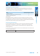
SAFETY INFORMATION Ordering the Correct Mains Lead When ordering a Confidence Monitor from Sonifex, it is helpful if you can specify your required operating voltage and mains lead. After the product code add: UK, for 230V, UK 3 pin to IEC lead EC, for 230V, European Schuko 2 pin to IEC lead US, for 115V, 3 pin to IEC lead Fig C: Mains Lead Table E.g. order RM-2CA2 UK for a UK IEC lead to be supplied.
WEEE & ROHS DIRECTIVE WEEE & RoHS Directives - Sonifex Statement WEEE & ROH S D I RE C T I VE The Waste Electrical and Electronic Equipment (WEEE) Directive was agreed on 13 February 2003, along with the related Directive 2002/95/EC on Restrictions of the use of certain Hazardous Substances in electrical and electronic equipment (RoHS).
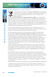
CONFIDENCE MONITORS INTRODUCTION The Confidence Monitor Range is a series of rack-mount audio monitors, combining the latest DSP technology with outstanding audio enclosure design to produce monitors of the highest standards with exceptional sound quality, a comprehensive feature set and good looks in the rack. Detail In The Design In the design of the product, every care has been taken to ensure the best and most accurate reproduction of the audio sources.
1 CONFIDENCE MONITORS INTRODUCTION DSP Based Design The use of a modern electronic architecture allows a much better audio performance to be realised. The DSP-based, 3rd-order active crossover provides perfect separation between mid-range and bass sounds. A DSP-based electronic equalisation is used to flatten the frequency response and the fastattack DSP loudspeaker limiter protects the drivers from overload damage.
CONFIDENCE MONITORS INTRODUCTION RM-CA2 1 Confidence Monitor, 2 LED Meters & 2 Analogue Stereo Inputs Fig 1-1: RM-CA2 Confidence Monitor Front Panel Sources are selected via a front panel push-button button, with clear LED indication of the current source.
1 CONFIDENCE MONITORS INTRODUCTION RM-CAD8 Confidence Monitor, 2 LED Meters, 2 Analogue & 6 Digital Stereo Inputs Fig 1-2: RM-CAD8 Confidence Monitor Front Panel CO NFIDE NCE MONITORS INTROD U C T I ON The RM-CAD8 has all the features of the RM-CA2 together with the ability to select from an additional 6 stereo digital inputs. As well as the 2 stereo analogue inputs there are also: • 1 x stereo S/PDIF unbalanced input on RCA phono female. • 1 x stereo TOSlink unbalanced input on an optical connector.
FRONT PANEL INDIC ATORS & CONTROLS 2 Front Panel Indicators & Controls Fig 1-4: RM-CA2 Front Panel Controls Power LED The POWER LED illuminates whilst internal power is present within the unit. If this indicator is not on, the most likely reason is simply the absence of mains power, but under fault conditions it may also indicate a ruptured mains fuse or a problem with the internal power supply module.
2 F RO N T PA NEL INDIC ATORS & CO N T RO LS Sync Lost indicator On the RM-CAD8 the Sync Lost indicator flashes when one of the following conditions is met. A digital audio input is selected and the digital audio signal is: • missing, • has a sample rate outside the acceptable range of the unit, • contains invalid/non-audio data, • or is too weak for the receiver to lock on to.
FRONT PANEL INDIC ATORS & CONTROLS 2 Level and Balance Controls Fig 1-10: RM-CAD8 Right Level Balance Control and Power On Indicator or Stereo Level Control There are two modes of operation for the level and balance controls determined by DIPSwitch 3. When the DIPSwitch is off, the level for each channel is independently controlled.
3 R E A R PA N EL CONNEC TIONS & O P E R AT I O NS LIMIT indicators RE AR PAN EL CON N EC TIONS & OP E R AT I ON S Limit active LED’s Fig 1-11: RM-CA2 & RM-CAD8 Meters & Phase Error LED The LIMIT indicators are an additional function of the left hand LED (-34 VU) of the meter scales. When the level potentiometer gain is applied to the incoming signals the resulting signal can exceed the maximum input levels into the D-class amplifier.
REAR PANEL CONNEC TIONS & OP ER ATION S 3 are as follows: Pin 1: Pin 2: Pin 3: Ground In-phase signal (“hot”) Out-of-phase signal (“cold”) Unbalanced signals may also be used by linking pins 1 and 3 and applying the unbalanced signal to pin 2. For the RM-CAD8 there is also an S/PDIF unbalanced digital stereo audio input on a RCA phono connector and a TOSLink optical digital stereo audio input.
3 R E A R PA N EL CONNEC TIONS & O P E R AT I O NS RE AR PAN EL CON N EC TIONS & OP E R AT I ON S DIPSwitch Settings 10 Fig 1-14: DIPSwitch Settings Reduce Meter Levels by 10dB - DIPSwitch 1 This DIPSwitch is only valid when analogue input 2 is selected and when the switch is on it will reduce the meter levels by 10dB. This switch will mainly be used when the unbalanced inputs are used.
T E C HNI C AL SP ECIFIC ATION R M - C A2 & RM - C AD 8 4 Technical Specification RM-CA2 & RM-CAD8 Inputs 2 x stereo analogue (1 x XLR balanced, 1 x XLR balanced or RCA phono unbal) Audio Inputs (RM-CAD8): 2 x stereo analogue (1 x XLR balanced, 1 x XLR balanced or RCA phono unbal) 4 x stereo XLR balanced AES/EBU digital 1 x stereo RCA phono S/PDIF digital 1 x stereo optical TOSLink digital Max Level (0dB Input Gain): +18dBu (analogue)/0dBFS (digital) CMRR: >60dB typical Analogue Input Impedances:
4 T E C H N I C AL S PE C I FI C AT I O N R M - C A 2 & R M - C A D8 TE CH NIC AL SPE CIFIC ATION RM - C A2 & RM - C A D 8 Amplifier/Loudspeakers 12 Configuration: Three-way with stereo mid/ high-frequency drivers & mono low-frequency driver Power Output: 2 x 7W (HF) + 15W (LF) with protective limiter Crossover: 250Hz (24dB/octave, Linkwitz-Riley) Distortion (HF Outputs): < 0.1% (1kHz, 3W output) Distortion (LF Output): < 0.
T E C HNI C AL SP ECIFIC ATION R M - C A2 & RM - C AD 8 Mains Input: Filtered 3-pin IEC male, continuously rated 85 - 264VAC, 47 - 63Hz, fused, 60W peak, 30W average Fuse Rating: Anti-surge fuse 2A 20 x 5mm 4 Equipment Type Confidence Monitor, 2 LED meters, 2 analogue stereo inputs RM-CAD8: Confidence Monitor, 2 LED meters, 2 analogue & 6 digital stereo inputs Physical Specification Dimensions (Raw): 48cm (W) x 27cm (D) x 4.4cm (H) (1U) 19” (W) x 12” (D) x 1.
w w w. s o n i fe x . c o. u k t:+44 (0)1933 650 700 f:+44 (0)1933 650 726 s a l e s @ s o n i fe x . co.