
Handbook
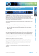
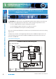
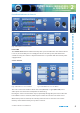
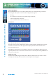
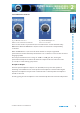
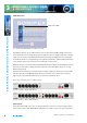
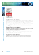
Table Of Contents
- Warranty
- Safety Information
- Installation Information
- Confidence Monitors Introduction
- RM-CA2 Confidence Monitor, 2 LED Meters &
- 2 Analogue Stereo Inputs
- RM-CAD8 Confidence Monitor, 2 LED Meters, 2 Analogue &
- 6 Digital Stereo Inputs
- Technical Specification RM-CA2 & RM-CAD8
- Fig A: Packing List
- Fig B: Power Connections
- Fig C: Mains Lead Table
- Fig 1-1: RM-CA2 Confidence Monitor Front Panel
- 
- Fig 1-3: Confidence Monitor Block Diagram
- Fig 1-4: RM-CA2 Front Panel Controls
- Fig 1-5: RM-CAD8 Front Panel Controls
- Fig 1-6: RM-CA2 Source Selector Button Fig 1-7: RM-CAD8 Source Selector Button
- Fig 1-8: RM-CA2 & RM-CAD8 Meters & Phase Error LED
- Fig 1-11: RM-CA2 & RM-CAD8 Meters & Phase Error LED
- Fig 1-12: Confidence Monitor RM-CA2 Rear
- Fig 1-13: Confidence Monitor RM-CAD8 Rear
- Fig 1-14: DIPSwitch Settings

4
Condence Monitors User Handbook
1
CONFIDENCE MONITORS
INTRODUCTION
CONFIDENCE MONITORS INTRODUCTION
RM-CAD8 Confidence Monitor, 2 LED Meters, 2 Analogue &
6 Digital Stereo Inputs
Fig 1-2: RM-CAD8 Condence Monitor Front Panel
The RM-CAD8 has all the features of the RM-CA2 together with the ability to select from an
additional 6 stereo digital inputs. As well as the 2 stereo analogue inputs there are also:
• 1 x stereo S/PDIF unbalanced input on RCA phono female.
• 1 x stereo TOSlink unbalanced input on an optical connector.
• 4 x stereo AES/EBU balanced inputs on XLR 3 pin female.
The source select button illuminates to indicate loss of synchronisation lock to the incoming
digital source.
A sample rate converter on the digital input allow sources of dierent sample rates to be
connected and monitored, between 32kHz and 96kHz. All other features of the unit are
identical to the RM-CA2.
System Block Diagram
Fig 1-3: Confidence Monitor Block Diagram
= Input Selector
A
= Metering
B
= Volume/Balance Control
C
= Overow Limiter
D
= Crossover & EQ
E
= Speaker Protection Limiter
F
Left
Speaker
Right
Speaker
Sub
Speaker
Inputs - RM-CA2 & RM-CAD8
Front Panel
Analogue
Inputs
A/D
Converters
D Class Amp
DSP
Digital
Audio
Receiver
Condence Monitors Block Diagram
2
3
4
5
6
7
8
2
1
Balanced
Optical
Unbalanced
E F
CB D
I/O Driver
Level
Controls
Headphone
Socket
Push
Button
Select
Indicator
Bargraphs Error
Indicator
Sync Lost
Indicator
RM-CAD8 only
Line Level
Outputs
D/A
Converters