
Handbook
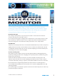
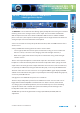
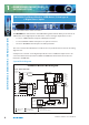
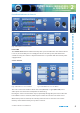
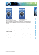
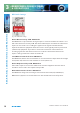
Table Of Contents
- Warranty
- Safety Information
- Installation Information
- Confidence Monitors Introduction
- RM-CA2 Confidence Monitor, 2 LED Meters &
- 2 Analogue Stereo Inputs
- RM-CAD8 Confidence Monitor, 2 LED Meters, 2 Analogue &
- 6 Digital Stereo Inputs
- Technical Specification RM-CA2 & RM-CAD8
- Fig A: Packing List
- Fig B: Power Connections
- Fig C: Mains Lead Table
- Fig 1-1: RM-CA2 Confidence Monitor Front Panel
- 
- Fig 1-3: Confidence Monitor Block Diagram
- Fig 1-4: RM-CA2 Front Panel Controls
- Fig 1-5: RM-CAD8 Front Panel Controls
- Fig 1-6: RM-CA2 Source Selector Button Fig 1-7: RM-CAD8 Source Selector Button
- Fig 1-8: RM-CA2 & RM-CAD8 Meters & Phase Error LED
- Fig 1-11: RM-CA2 & RM-CAD8 Meters & Phase Error LED
- Fig 1-12: Confidence Monitor RM-CA2 Rear
- Fig 1-13: Confidence Monitor RM-CAD8 Rear
- Fig 1-14: DIPSwitch Settings

Condence Monitors User Handbook
5
2
FRO N T PANEL INDICATO R S
& CONTROLS
FRONT PANEL INDICATORS & CONTROLS
Front Panel Indicators & Controls
Fig 1-4: RM-CA2 Front Panel Controls
Fig 1-5: RM-CAD8 Front Panel Controls
Power LED
The POWER LED illuminates whilst internal power is present within the unit. If this indicator
is not on, the most likely reason is simply the absence of mains power, but under fault
conditions it may also indicate a ruptured mains fuse or a problem with the internal power
supply module.
Source Selector
Fig 1-6: RM-CA2 Source Selector Button Fig 1-7: RM-CAD8 Source Selector Button
The Source Selector determines which of the two (RM-CA2) or eight (RM-CAD8) stereo
audio inputs is routed to the loudspeakers and metering.
Pressing the Source selector button steps sequentially through all input sources. Once the
last available source is selected, a further press returns the selection to the first source.
When mains power is removed, the currently selected Source is stored in non-volatile
memory and recalled instantly once power is restored.