
Handbook
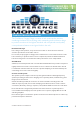
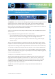
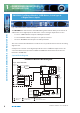
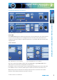
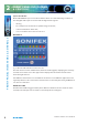
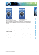
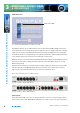
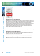
Table Of Contents
- Warranty
- Safety Information
- Installation Information
- Confidence Monitors Introduction
- RM-CA2 Confidence Monitor, 2 LED Meters &
- 2 Analogue Stereo Inputs
- RM-CAD8 Confidence Monitor, 2 LED Meters, 2 Analogue &
- 6 Digital Stereo Inputs
- Technical Specification RM-CA2 & RM-CAD8
- Fig A: Packing List
- Fig B: Power Connections
- Fig C: Mains Lead Table
- Fig 1-1: RM-CA2 Confidence Monitor Front Panel
- 
- Fig 1-3: Confidence Monitor Block Diagram
- Fig 1-4: RM-CA2 Front Panel Controls
- Fig 1-5: RM-CAD8 Front Panel Controls
- Fig 1-6: RM-CA2 Source Selector Button Fig 1-7: RM-CAD8 Source Selector Button
- Fig 1-8: RM-CA2 & RM-CAD8 Meters & Phase Error LED
- Fig 1-11: RM-CA2 & RM-CAD8 Meters & Phase Error LED
- Fig 1-12: Confidence Monitor RM-CA2 Rear
- Fig 1-13: Confidence Monitor RM-CAD8 Rear
- Fig 1-14: DIPSwitch Settings

6
Condence Monitors User Handbook
2
FRO N T PANEL INDICATO R S
& CONTROLS
FRONT PANEL INDICATORS & CONTROLS
Sync Lost indicator
On the RM-CAD8 the Sync Lost indicator flashes when one of the following conditions is
met. A digital audio input is selected and the digital audio signal is:
• missing,
• has a sample rate outside the acceptable range of the unit,
• contains invalid/non-audio data,
• or is too weak for the receiver to lock on to.
Main Meters
Fig 1-8: RM-CA2 & RM-CAD8 Meters & Phase Error LED
The main meters are twin 8-LED cluster, multicoloured bargraphs, displaying the currently
selected stereo audio source. The upper meter displays the left channel and the lower
meter the right channel.
Two different characteristics are available for the meters to suit different applications and
regional preferences. The active meter characteristic is selected by the setting of DIPSwitch
7 on the rear of the unit.
PHASE Error LED
The Phase Error LED is triggered if the phase difference between the two channels of the
currently selected input source remains consistently above 135 degrees.