
Handbook
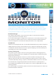
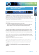
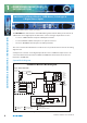
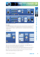
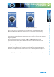
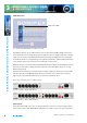
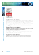
Table Of Contents
- Warranty
- Safety Information
- Installation Information
- Confidence Monitors Introduction
- RM-CA2 Confidence Monitor, 2 LED Meters &
- 2 Analogue Stereo Inputs
- RM-CAD8 Confidence Monitor, 2 LED Meters, 2 Analogue &
- 6 Digital Stereo Inputs
- Technical Specification RM-CA2 & RM-CAD8
- Fig A: Packing List
- Fig B: Power Connections
- Fig C: Mains Lead Table
- Fig 1-1: RM-CA2 Confidence Monitor Front Panel
- 
- Fig 1-3: Confidence Monitor Block Diagram
- Fig 1-4: RM-CA2 Front Panel Controls
- Fig 1-5: RM-CAD8 Front Panel Controls
- Fig 1-6: RM-CA2 Source Selector Button Fig 1-7: RM-CAD8 Source Selector Button
- Fig 1-8: RM-CA2 & RM-CAD8 Meters & Phase Error LED
- Fig 1-11: RM-CA2 & RM-CAD8 Meters & Phase Error LED
- Fig 1-12: Confidence Monitor RM-CA2 Rear
- Fig 1-13: Confidence Monitor RM-CAD8 Rear
- Fig 1-14: DIPSwitch Settings

Condence Monitors User Handbook
7
2
FRO N T PANEL INDICATO R S
& CONTROLS
FRONT PANEL INDICATORS & CONTROLS
Level and Balance Controls
Fig 1-9: RM-CA2 Left Level or Fig 1-10: RM-CAD8 Right Level
Balance Control and Power On Indicator or Stereo Level Control
There are two modes of operation for the level and balance controls determined by
DIPSwitch 3. When the DIPSwitch is o, the level for each channel is independently
controlled.
When the DIPSwitch is on, the level for both channels is set by the right hand
potentiometer and the left hand potentiometer acts as a balance control to alter the stereo
imaging by ±6dB.
The level potentiometers have a range of -52dB to +18dB gain. Also, moving the
potentiometer fully anti-clockwise will mute the output. Position 6 on the level scale
(1 o’clock) is a nominal unity gain position.
Headphone Output
The front panel headphone output is a ¼” (6.35mm) stereo jack socket capable of
delivering over 80mW into 32Ω - 600Ω professional headphones at full volume. Higher
impedance headphones may be used at reduced levels. Lower impedance headphones
should not be used.
Inserting a plug into the headphone socket automatically mutes the internal loudspeakers.