
Handbook
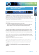
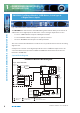
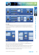
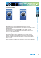
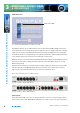
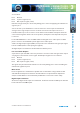
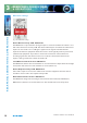
Table Of Contents
- Warranty
- Safety Information
- Installation Information
- Confidence Monitors Introduction
- RM-CA2 Confidence Monitor, 2 LED Meters &
- 2 Analogue Stereo Inputs
- RM-CAD8 Confidence Monitor, 2 LED Meters, 2 Analogue &
- 6 Digital Stereo Inputs
- Technical Specification RM-CA2 & RM-CAD8
- Fig A: Packing List
- Fig B: Power Connections
- Fig C: Mains Lead Table
- Fig 1-1: RM-CA2 Confidence Monitor Front Panel
- 
- Fig 1-3: Confidence Monitor Block Diagram
- Fig 1-4: RM-CA2 Front Panel Controls
- Fig 1-5: RM-CAD8 Front Panel Controls
- Fig 1-6: RM-CA2 Source Selector Button Fig 1-7: RM-CAD8 Source Selector Button
- Fig 1-8: RM-CA2 & RM-CAD8 Meters & Phase Error LED
- Fig 1-11: RM-CA2 & RM-CAD8 Meters & Phase Error LED
- Fig 1-12: Confidence Monitor RM-CA2 Rear
- Fig 1-13: Confidence Monitor RM-CAD8 Rear
- Fig 1-14: DIPSwitch Settings

8
Condence Monitors User Handbook
REAR PANEL CONNECTIONS
& OPERATIONS
3
REAR PANEL CONNECTIONS & OPERATIONS
LIMIT indicators
Limit active LED’s
Fig 1-11: RM-CA2 & RM-CAD8 Meters & Phase Error LED
The LIMIT indicators are an additional function of the left hand LED (-34 VU) of the meter
scales. When the level potentiometer gain is applied to the incoming signals the resulting
signal can exceed the maximum input levels into the D-class amplier. To avoid clipping
or overow conditions a limiter function is applied. The limiter is applied independently to
each channel and has an instantaneous attack with a slow release.
While the limiter is active the left hand LED will ash. If the LED is continually ashing then
the level potentiometer setting should be reduced so that the LED is always on or only
ashes infrequently.
Note that for the limiter to be required the incoming signal level will need to exceed 0dB
(VU -4). If the left hand LED is ashing but the meter levels are low then the incoming
signal is lower than VU 34 and this does not indicate a limiter function.
Rear Panel Connections & Operation
Fig 1-12: Confidence Monitor RM-CA2 Rear
Fig 1-13: Confidence Monitor RM-CAD8 Rear
Audio Inputs
Three-pin female XLR connectors are provided for the connection of two analogue stereo
audio sources and for the RM-CAD8 four digital stereo audio sources. The pin assignations