
Handbook
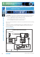
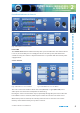
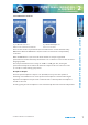
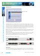
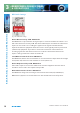
Table Of Contents
- Warranty
- Safety Information
- Installation Information
- Confidence Monitors Introduction
- RM-CA2 Confidence Monitor, 2 LED Meters &
- 2 Analogue Stereo Inputs
- RM-CAD8 Confidence Monitor, 2 LED Meters, 2 Analogue &
- 6 Digital Stereo Inputs
- Technical Specification RM-CA2 & RM-CAD8
- Fig A: Packing List
- Fig B: Power Connections
- Fig C: Mains Lead Table
- Fig 1-1: RM-CA2 Confidence Monitor Front Panel
- 
- Fig 1-3: Confidence Monitor Block Diagram
- Fig 1-4: RM-CA2 Front Panel Controls
- Fig 1-5: RM-CAD8 Front Panel Controls
- Fig 1-6: RM-CA2 Source Selector Button Fig 1-7: RM-CAD8 Source Selector Button
- Fig 1-8: RM-CA2 & RM-CAD8 Meters & Phase Error LED
- Fig 1-11: RM-CA2 & RM-CAD8 Meters & Phase Error LED
- Fig 1-12: Confidence Monitor RM-CA2 Rear
- Fig 1-13: Confidence Monitor RM-CAD8 Rear
- Fig 1-14: DIPSwitch Settings

Condence Monitors User Handbook
9
3
REAR PANEL CONNECTIONS
& OPERATIONS
REAR PANEL CONNECTIONS & OPERATIONS
are as follows:
Pin 1: Ground
Pin 2: In-phase signal (“hot”)
Pin 3: Out-of-phase signal (“cold”)
Unbalanced signals may also be used by linking pins 1 and 3 and applying the unbalanced
signal to pin 2.
Source two has a pair of RCA Phono connectors that are used to input an unbalanced
analogue stereo signal input 2 sources are both connected to the input selector as a
hard-wired mix. If you connect sources to the balanced and unbalanced inputs then both
sources mixed together will be sent to the speakers, headphone and output when input 2
is selected.
For the RM-CAD8 there is also an S/PDIF unbalanced digital stereo audio input on a RCA
phono connector and a TOSLink optical digital stereo audio input.
A full-scale digital input signal (0dBFS) corresponds to the maximum analogue input signal
level of +18dBu (with no extra input gain applied).
All digital inputs are terminated 110Ω for XLR and 75Ω for phono.
Line Level Audio Outputs
A pair of three-pin male XLR connectors provides a stereo line-level analogue audio output
carrying the selected audio Source signal. The XLR pin assignations are as follows:
Pin 1: Ground
Pin 2: In-phase signal (“hot”)
Pin 3: Out-of-phase signal (“cold”)
The signals may be unbalanced without loss of level by linking pins 1 and 3 and taking the
unbalanced signal from pin 2.
Mains Power
Power is applied via a standard three-pin IEC male socket. Mains voltages between 85V
and 264V AC and frequencies between 47 and 63Hz are accepted without adjustment.
A 2A, 5 x 20mm SB fuse is used. The Earth pin MUST be connected to ensure safety.
Digital Input Termination
All electrical digital audio inputs are terminated. 110Ω for the balanced XLR inputs and 75Ω
for the unbalanced S/PDIF inputs.