
Installation Guide


©2016 SONNEMAN - A WAY OF LIGHT
2 of 3
October 20, 2016
Assembly Instructions
INSTRUCTIONS D’INSTALLATION
REALS Series - 16" LED Bollard, 22" LED Bollard, 28" LED Bollard
16" LED Double Bollard, 22" LED Double Bollard, 28" LED Double Bollard
Important
• Always disconnect the power before installing or replacing bulbs and before cleaning or other maintenance.
• Consult a qualied, licensed electrician to ensure correct branch circuit conductor.
Consulter un électricien qualié pour vous assurer que les conducteurs de la dérivation sont adéquats.
1. Shut off power to the branch circuit conductor.
2. Install a 12VAC output magnetic transformer in an accessible location,
and run low voltage outdoor power cable (A) from the transformer to the
desired bollard location in accordance with local codes. To avoid
excessive voltage drop, you must use power cable with appropriate wire
gauge for the distance and load of your system. The REALS bollards can
accept an input voltage from 10 to 15VAC.
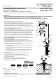
3. For Concrete Mounting: Using the provided temporary template (Fig. 1),
cast the anchor bolts (B) and low voltage outdoor power cable (A) into a
concrete footing (C). Arrange the anchor bolts so that they are vertical
and form an arrow pointing in the desired direction of the xture (D),
with at least 1/2" of threaded and no unthreaded length exposed above
the concrete. Arrange the power cable so that it is in the center of the
template, with at least 6" of cable exposed above the concrete.
4. For Concrete Mounting: Once the concrete (C) has fully cured, remove
and discard the template.
5. For Concrete Mounting: Place mounting plate (E) over the
anchor bolts (B) and power cable (A). Secure with mounting nuts (F).
For Wood Mounting: Place mounting plate (E) over the power cable (A)
and secure with lag screws (not included).
6. Make appropriate electrical connections using outdoor wire nuts (G):
a. Connect one of the power cable conductors to one of the xture's
input conductors.
b. Connect the other power cable conductor to the xture's other
input conductor.
c. Carefully place the conductors and connections into the post (H).
7. Place the post (H) over the mounting plate (E). Secure with
mounting screws (J).
8. Install the cap (K) to the top of the xture (D). Secure with the
cap screws (L) using the included Allen wrench (M).
Warning: Do not touch or press on the LEDs inside the xture,
or they will be damaged.
9. Screw the lens (N) to the bottom of the xture (D).
For the Plate Lens, tighten using the included tool (P).
10. Restore power to the xture.
Note
• This xture is not dimmable.
Care Instructions
• Dusting: Use a clean, dry cloth.
• Cleaning: To protect the nish, avoid any harsh abrasives or chemicals.
7303, 7304, 7305
7306, 7307, 7308
E
F
H
G
J
N
P
L
M
D
K
A
B
B
A
C
DL -
Dome Lens
FH -
Clear Cylinder
Lens
FW -
White Cylinder
Lens
PL -
Plate Lens
DC -
Dome Cap
PC -
Plate Cap