
Installation & Assembly

Important: Always disconnect the power before installing or replacing bulb and before cleaning or other maintenance.
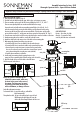
Assembly Instructions for item : 2602
©2014 SONNEMAN - A WAY OF LIGHT
This light should be installed by a licensed electrician
CARE INSTRUCTIONS
Dusting – Use a clean, dry cloth.
Cleaning – To protect the finish,
avoid any harsh abrasives or chemicals.
Steel cable adjustment instructions:
To shorten the cable - Just push the cable up, cable will be
locked automatically.
To lengthen the cable - Lift up on the cable and push up on the lock.
While keeping the lock depressed, lower the
cable to the desired length. Release the lock to set.
Chromaglo
TM
Spectrum Series - Square Reflector Pendant
LAMP INSTALLATION AND ASSEMBLY
1. Shut off power to the outlet box. (fig. A)
2. Feed the cords and cable through the stems, holes in glass, and grippers on canopy.
3. There are markings on the top of the LED housing, labeling the cords “A”, “B”, and “C”.
There are corresponding labels next to each terminal block in the canopy.
Connect the cords and cable to the corresponding terminal blocks (A to A, B to B, C to C)
inside the canopy by firmly pressing the tabs until they are fully depressed and inserting
the wires into the correct holes on the correct terminal block. The inner wires and the cable
go into the holes marked “L”, and the outer mesh wires go into the holes marked “N”. (Fig. 1)
4. Screw the stems into the holes on LED housing, and place the glass onto the shoulders on the stems.
5. Attach mounting plate to the outlet box, secure with outlet box screws.
6. Attach the safety hook in the canopy to one of the holes on the mounting plate.
7. Make appropriate electrical connections using wire nuts:
a. Connect the LED driver’s live wire (black) to the live outlet box wire.
b. Connect the LED driver’s neutral wire (white) to the neutral outlet box wire.
c. Connect fixture’s ground wire (green or uncoated) to the ground outlet
box wire. If no ground is present in outlet box, connect fixture’s ground
wire to the mounting plate using the green screw (included).
d. Carefully place connections in outlet box.
8. Install canopy to mounting plate by inserting the pins on the
canopy into slots on mounting plate. Slide the canopy to the side to lock.
9. Adjust the lengths of the cords and cables to level the fixture.
10. Restore power to the fixture.
NOTE: This fixture is controlled by the
included IR remote control, which must
be aimed at the sensor in the center of
the canopy. The fixture may be turned
on/off by a wall switch, but do not use
with a wall dimmer, or damage will occur.
outlet box
canopy
mounting plate
outlet box screw
pin
gripper
push
power cord
steel cable
glass
LED housing
stem
shoulder
Fig. 1
outer mesh
wire
inner wire
cable
outer mesh
wire
inner wire
tab
safety hook
slot
LED driver
lock
sensor
L NA
A
L NB
B
L N
C
C