
Installation & Assembly


October 31, 2019
©2019 SONNEMAN - A WAY OF LIGHT
Appendix A
Fig. 1 Fig. 2
Fig. 3 Fig. 4
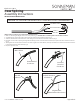
If eld-cutting is required, please follow the below instructions:
1. Make a 1” slice along the length of the cord's outer jacket (Fig. 1). CAUTION: Do not cut through the outer braided conductor.
2. Carefully strip the outer jacket of the cord and keep the outer braided conductors intact (Fig. 1).
3. Slide the outer braided conductor back to create a bulge and reveal the inner stranded conductor (Fig. 2).
4. Bend the cord to create an opening through the bunched-up portion of outer braided conductor, then pull out the inner stranded conductor
(Fig. 3)
5. Twist together the outer braided conductor to form the negative wire of the xture, then strip 5/8” o the end of the inner stranded conductor
to form the positive wire of the xture (Fig. 4).
6. Re-splice all power cords.
Outer Braided
Conductor
Outer Jacket
Insulated
Stranded
Conductor
Insulated
Stranded
Conductor
Negative Wire
(Outer Braided Conductor)
Positive Wire
(Insulated Stranded
Conductor)
Coax Splicing
Assembly Instructions
INSTRUCTIONS D’INSTALLATION
FAILURE TO FOLLOW THESE INSTRUCTIONS WILL VOID THE WARRANTY
Inner Stranded Conductor
End
View
Insulation
Outer Jacket
Outer Braided Conductor
Coaxial Power Cord: