Sonnox Oxford Dynamics Operation Manual Version 1.
1. Introduction The Oxford Dynamics plug-in is a direct emulation of the extremely flexible and capable unit used in the OXF-R3 professional mixing console. Resulting from many years research into professional dynamics applications, it offers separate Compressor, Limiter, Expander, Gate and sidechain EQ functions, with fully independent control of all parameters.
Dynamic signal level control has grown in complexity and popularity from humble beginnings to an essential part of the sound production process. Originally conceived as a method to automatically correct for performance variation and broadcast transmission limitations, dynamic control has evolved beyond this to engender complete artistic cultures and idioms, resulting from the continuous expansion of the artistic effects provided by such processes.
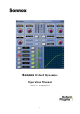
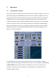
2. Operation 2.1 ‘Front Panel’ Controls The separate dynamics functions have their own control sets that are available at any time by operating the appropriate ACCESS button for that section. Operating the IN button for any section will force the controls for that section to the foreground of the GUI for convenience. The IN buttons can be used to toggle the contributions from each section on and off, for comparison purposes.
A live graphic display of the overall level transfer function is permanently displayed (in the lower right) for reference, and all setting parameter values are visible for any section that is being accessed. 2.2 Dynamics Control The Dynamics section comprises of four separate applications, Compressor, Limiter, Gate and Expander.
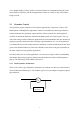
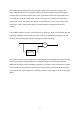
This method had an advantage in early analogue compressors because the complex and largely unpredictable laws of early gain reduction elements could be somewhat decoupled from the total level transfer characteristic of the application (because the design made use of level feedback).
2.3 Compressor There are two main factors that describe the function of a compressor: a level versus gain function, which is generally assumed to be independent of the time constants, and a dynamic gain function which exhibits more complex dynamic behaviour over time. To explain the operation of the compressor section, it is useful to split these two categories. The following section refers to the level versus gain behaviour of the compressor application in the Oxford Dynamics plug-in.
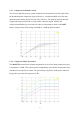
2.3.1 Compressor Threshold Control The threshold control sets the level (referred to dBFS) at which compression and gain reduction will begin. The control has a linear decibel law over the range. The following graph illustrates the threshold control operated in 5dB increments with the ratio at max (1000:1) to –20dBr. 2.3.2 Compressor Ratio Control The ratio control sets the rate at which gain reduction will occur when the input level goes beyond the set threshold level.
2.3.3 Compressor Soft Ratio Control The soft ratio function provides a gentle, minimum rate transition between the region below the threshold and the compressed region of the curve. A further threshold, below the main threshold control setting, defines the start of the soft curve. The program signal is therefore compressed progressively harder as it gets louder within this region, until the full compression defined by the ratio control is achieved.
2.3.5 Using Level Control Functions Since all level control functions in the Oxford Dynamics Compressor operate entirely separately, a very high degree of control for a wide range of common use is possible, in particular the plug-in does not impose any particular style constraint on the user. This section explains some of the commonly used techniques, and how they may be achieved using the Dynamics plug-in.
2.3.6.1 ‘Least Possible’ Approach The first and most obvious, which we will call the ‘least possible’ approach, is to leave the majority of the programme uncompressed, forcing the compression to deal only with the louder passages. This method has a definite psychological advantage in that one gets the feeling that the majority of the programme remains unaffected.
One way to alleviate the compression transition effect is to smooth it out using the soft ratio function: The above graph shows the action of the SOFT ratio control set to 5dB applied to the previous settings. Starting the compression earlier, and increasing the compression ratio up to the max level point, smoothes out the transition point at the onset of compression.
2.3.6.2 ‘Overall Compression’ Approach This concept advocates that a more transparent sounding compression can be achieved if a relatively large portion of the programme level range is under continuous compression. The rationale here is that the rate of change disturbances are minimised because the compressor spends less time going over the onset of compression transition range.
2.3.6.3 Combined Approach From the above discussion we can see that the digital compressor, with its sonically transparent gain control process and very accurate level control, allows very effective influence over a wide dynamic range of programme material, without incurring some of the problems associated with analogue units.
Minimum Obtrusion This graph shows a minimum intrusion type curve using a ratio of around 2:1 and a soft ratio setting of 10dB. This style of compression will bring up the softer passages by around 12dB and progressively compress the loud passages into half the original dynamic range — in a very subtle and unobtrusive fashion.
2.3.7 Timing Functions The relationship between gain compression and temporal behaviour is absolutely crucial to successful dynamic control, whether the user is aiming for the unobtrusive control of levels or a completely stylised sound effect. Much of the artistic character in the massive range of renowned compressors is determined by subtleties in the timing behaviour of these units under complex musical signal conditions.
2.3.7.1 Compressor Attack Control The attack control varies the timing behaviour of the compressor at the onset of gain reduction, either due to the arrival of a peak level above the threshold or the further increase in a level already above the threshold. " The three diagrams above show the action of the attack control from minimum through mid range to maximum setting.
2.3.7.2 Compressor Release Control The release control varies the timing behaviour of the compressor during the recovery period after a gain reduction, when the signal level has reduced from previous levels above the threshold. The above diagrams show that action of the release control from minimum to half range (maximum range is too long to show successfully on this diagram).
2.3.7.3 Compressor Hold Control The hold control varies the amount of time between a reduction of levels above the threshold and the onset of the release time. It provides a period after gain reduction where a slower rate of recovery occurs. The above three diagrams show the action of the hold control from nearly minimum to 75% of maximum, with an intermediate position with the release set to minimum.
2.3.8 Compressor Timing Laws The Oxford compressor offers three compression types designated NORMAL, CLASSIC and LINEAR, selected sequentially via a button in the centre of the Dynamics display. The time constant laws employed define the major difference between these types.
2.3.8.1 Exponential/dB timing (Normal and Classic types) The Exponential/dB curve is by far the most popular law used in a great many well-respected compressors, and is the natural result of more recent analogue units employing logarithmic sidechains and resistor/capacitor time constants. The Exponential/dB law has some interesting characteristics. First, the time taken to complete a compression event tends to stay the same however large the dynamic signal excursion is.
2.3.8.2 Linear/dB timing (Linear type) The Linear /dB law, in some respects, exhibits the reverse behaviour of the Exponential law. Because the rate of change of gain is constant (as set by the timing controls), the greater the signal dynamic excursion the longer the compressor will take to complete a gain change.
2.3.9 Using Compression Timing Functions The setting of timing functions can drastically affect the sonic character of compression, and there are many different approaches to compression timing, often in pursuit of ever-changing fashion! There is, therefore, no right or wrong approach to this task. However, to successfully build up your own portfolio of artistic sounds using a variable parameter compressor such as the Oxford plug-in, a basic grounding in the sonic effects produced by timing will be useful.
The following provides a general description of some effective approaches and starting points: 2.3.9.1 Fast as Possible Approach To obtain absolute maximum modulation and minimum dynamic range, the best approach is to set release times to minimum, increase the hold time just enough to the reduce LF distortion to acceptable levels, and increase the attack time just enough to allow some overshoot on percussive peaks, in order to retain some impression of programme dynamics.
2.3.9.4 Artistic Effects The manipulation of timing within compression can create some very useful effects. In particular, gain overshoots produced by slow to moderate attack times can be very useful at tightening up soft percussion sounds. However, a note of caution is needed for users of workstation applications in that effects such as these may cause unexpected programme clipping that may prevent the available range of possible sounds being fully appreciated.
2.4 Limiter From a level profile perspective, a limiter is essentially the same as a compressor with its ration set to infinity. However, the use of much faster attack times with a somewhat different dynamic behaviour allows faster and more effective reduction of peak levels. Historically, limiters were developed mainly for radio transmission systems where absolute limits on modulation were needed.
2.4.1 General Description The limiter’s controls are presented similarly to the compressor’s except that there is no ratio control. The time constant functions, although similar to the compressor, have different ranges. In particular the attack time can be adjusted to be much faster than the compressor.
2.4.2 General Limiter Operation There are many methods and approaches to programme limiting that are favoured amongst users. In general however, these fall into the two main categories described below. The least intrusive kind of limiting is achieved with a fast attack and a relatively slow release, adjusted to suit the general timing of the music. Very long decays, often favoured in classical music productions, can be achieved with the Oxford limiter by using a combination of both release and hold times.
2.5 Expander The dynamics’ Expander section control functions are presented similarly to the Compressor and Limiter sections, except that a RANGE control is added. The architecture of the expander conforms to what is often described as ‘downward expansion’, which means that the application only works to attenuate existing signals below a set threshold, and cannot produce any additional gain for signals above the set threshold level.
Expanders may be used for many purposes, both technically and artistically. These include background noise reduction and file clean up, the reduction of ambient noise disturbance in live recordings, presence and dynamic profiling of instruments, and creative control of ambient reverb etc.
The Oxford plug-in Gate has many advanced design subtleties that are based on long experience in the artistic use of gating. The basic architecture of a gate is similar to an expander with infinite ratio, and therefore acts much like a programme switch. Signals below the set threshold are cut and only those above this are passed to the output.
2.7 Sidechain EQ A high specification two-band Sidechain EQ (S-C EQ) is provided to allow de-essing and other modifications of sidechain frequency response. The EQ processing section may be routed to either the dynamics sidechain or the main signal path or both simultaneously, by selection of the independent EQ-SC and EQ SIGNAL buttons. 2.7.1 Sidechain EQ Controls All Gain, Frequency and Q controls operate separately, and their values are displayed permanently.
HF Q — Controls HF Q from 0.5 to 16. HF FREQ — Controls the HF section frequency from 500Hz to 20KHz. HF GAIN — Controls LF gains between -20dB and +20dB. LF SHELF and HF SHELF — Individually select shelving responses for LF and HF sections. INPUT GAIN* — Adjusts the input level to the EQ section from –20dB to 0dB to avoid EQ clipping when in boost settings. EQ S-C — Routes the EQ processing into the sidechain. EQ SIGNAL — Routes the EQ processing into the main signal path.
2.8 Warmth The WARMTH process confers additional loudness, punch and definition to the sound of the dynamics section. The operation of this process is to impose a harmonic profile onto the signal that increases the density of higher value samples within the programme, in order to boost average modulation levels without an increase in peak levels or the risk of digital clipping. The Warmth function is engineered to achieve this without the loss of dynamic information within the programme material.
The process also adds subtle warmth to the programme material that is reminiscent of valve systems, and is similarly tolerant of overloaded or previously clipped signals, avoiding much of the harshness associated with these conditions. Significant artistic effects may therefore be achieved by deliberately overdriving the Warmth processing by increasing the compressor gain make-up beyond normal levels and allowing the Warmth processing to control the peak signal levels.
2.11 Buss Compressor (Pro Tools TDM only) 2.11.1 General Description The Buss Compressor is a separate instantiation that allows full multi-format compression and limiting with Sub channel generation and control (up to 5.1). The Compressor, Limiter and Warmth processes are identical to the channel dynamics plug-in (as described in the preceding sections of this manual), but the Expander and Gate functions are removed to release processing load for extended multi-format application.
2.11.2 Description of Controls The ‘front panel’ controls generally operate similarly to the channel compressor. The functions are listed below. 1. IN Buttons — Toggle section contributions in and out for comparison purposes. Selecting IN for a main function will also force ACCESS to that section’s controls. 2. ACCESS Buttons — Accesses controls for that section. 3. INPUT and OUTPUT Metering — Provide a permanent display of input and output levels for each contribution to the surround buss. 4.
6. External Key Input Selector (Pro Tools only) — Selects externally derived signal to the sidechain input. 7. Soft Ratio Selector — Selects soft ratio starting threshold in 5dB steps to –20dB below threshold control setting. 8. RATIO — Controls the ratio of the compressor and expander processes. It is inoperative in limiter and gate functions. 9. THRESHOLD — Controls the threshold of compressor or limiter function as selected. 10.
2.11.3 Buss Compressor Architecture The Buss Compressor employs common sidechain processing to all buss contributions simultaneously. This avoids unwanted modification to panning and balance during compression gain changes, but it does mean that parameter settings will apply to all main busses and increased level on any buss will result in increased compression on all outputs.
2.11.4 Description of Sub Channel Controls 1. ACCESS Button — Accesses controls for the Sub channel processing. 2. IN Button — Toggles Sub filter in and out of the signal path. 3. LP FILTER — Sets the Sub channel filter cut off frequency between 50Hz and 150Hz (at 24dB/octave). 4. SUB PASS — Sets the proportion of the compressor contribution to the Sub channel gain, from 0 – 100%. 5. SUB TRIM — Sets the proportion that the Sub channel signal contributes to the compressor sidechain, from 0 – 100%.
Note that with SUB PASS and SUB TRIM controls both set to 100%, the sub channel will be completely included in the compression function, and be treated just like the main channels. With both controls set at 0%, the Sub channel will be completely independent and will not be included in, or affected by, the Dynamics functions.
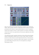
3. Description of Controls This section provides a summary of the ‘front panel’ controls you will encounter when using the various sections of the Dynamics plug-in (the illustration below is of the Compressor controls): IN Buttons — toggle section contributions in and out for comparison purposes. Selecting IN will also force ACCESS to that section’s controls. ACCESS Buttons — accesses controls for that section. INPUT and OUTPUT metering — provides a permanent display of overall input and output levels.
SOFT RATIO Selector — selects the soft ratio starting threshold in 5dB steps to –20dB below threshold control setting. RATIO — controls the ratio of the compressor and expander processes. It is inoperative in limiter and gate functions. THRESHOLD — controls the threshold of any dynamics function selected. ATTACK — controls the attack time of any dynamics function selected. HOLD — controls the hold time of any dynamics function selected. RELEASE — controls the release time of any dynamics function selected.
Knob Modes – Four options determine how the rotary controls (knobs) behave: With Circular Knob Mode the control is set to the value at which it is first clicked, and the value then increases or decreases with circular mouse movement. In Relative Circular Knob Mode a control’s value increases or decreases with circular mouse movement relative to its initial value. Linear Knob Mode increases or decreases a control’s value with up and down mouse movements respectively.
4. Preset Manager Toolbar The Oxford Dynamics plug-in comes equipped with its own onboard Preset Manager, which is displayed as a toolbar at the top of the plug-in window, just as if the host created it (see above). The reasoning behind this is to allow increased portability of your presets across all the host applications, while also providing a consistent and versatile interface.
5. Specifications Section Threshold Ratio/Range Gate Expander Compressor Limiter -80 – 0dB -60 – 0dB -60 – 0dB -60 – 0dB 0 - -80dB 0 - -80dB 1:1 - Limit Gain Make-up Attack Hold 5uS* - 26mS 0.26 – 104mS 519uS – 52mS 100uS – 500mS 10mS – 10S 10mS – 20S 10mS – 30S 50mS – 30S Soft Curve Release 7.8 – 519mS 5.2 – 519mS 52mS – 3.
6. Copyright and Acknowledgements Trademarks and content copyright © 2007-Present Sonnox Ltd. All rights reserved. This Product is manufactured and supplied by Sonnox Ltd. under licence from Sony UK Ltd. The following patents protect this Product: GB2330747, GB2310983, GB2310984, GB2310985, GB 2342023, US5923767, US5923768 DIGIDESIGN, AVID, and PRO TOOLS are trademarks or registered trademarks of Digidesign and / or Avid Technology, Inc. VST is a Trademark of Steinberg AG.
Platform Specific Supplement S1. Supported Platforms Avid Pro Tools (LE, RTAS, M-Powered, Pro Tools HD) and Pro Tools 10 (HDX & Native) VST Native Audio Units Native S2. System Requirements These requirements are current at this revision of manual. For latest system requirements, please see the website www.sonnox.com Pro Tools Pro Tools 7, 8, 9 & 10 Approved Pro Tools CPU, OS and hardware configuration (see www.avid.com) Mac OSX 10.