
Home Theater System User Manual

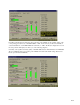

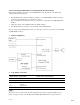
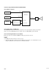
Table Of Contents
- Cover
- Table of Contents
- Check list
- 1. Introduction
- 2. Equipment and accessories
- 3. Basic checks of site and installation
- 4. Checks of correct DFP-R3000 Reader mounting
- 5. A-Chain alignment using DFP-D3000 front panel controls
- 6. B-Chain Alignment
- 7. Overall systems check and listening test
- 8. Troubleshooting
- 9. Appendix
- 9.1 DFP-D3000 Rear Panel Connector Pin Assignment
- 9.2 DFP-D3000 Input/Output Level
- 9.3 Changeover Settings
- 9.4 Settings for using DFP-D3000 as DFP-D2000
- 9.5 Description on Connection of DA-20 and DFP-D3000
- 9.6 Connecting the CP-500 and DFP-3000
- 9.7 Connecting the DTS-6, DTS-6D and DFP-D3000
- 9.8 Corresponding to DFP-D3000 Surround EX
- 9.8.1 Restrictions on Control of Surround EX Decoder
- 9.8.2 Connections of Audio System
- 9.8.3 Actual Connection of Control System
- 9.8.4 SA-10 Operations When Controlling from the DFP-D3000
- 9.8.5 Controlling Surround EX from DA-20
- 9.8.6 Controlling Surround EX from DTS-6 or DTS-6D
- 9.8.7 Controlling Surround EX control from Automation Controller
- 9.8.8 Adjustments of Audio System
- 9.9 Test Cable for Performing A-Chain Adjustment
- 9.10 Adjusting the Analog Track Pickup
- 9.10.1 Preliminary Preparations Before Adjustments
- 9.10.2 Lateral Film Guide Adjustment
- 9.10.3 Lateral Exciter Lamp Adjustment
- 9.10.4 Lateral Solar Cell Adjustment
- 9.10.5 Vertical Adjustment of Exciter Lamp
- 9.10.6 Slit Lens Adjustment
- 9.10.7 Double Checking of Illumination Inconsistency
- 9.10.8 Wiring Check
- 9.11 Description of the DFP-D3000 Setup Software Menus
- 9.11.1 Start-up Screen
- 9.11.2 Description of File Menu Items
- 9.11.3 Description of Config Menu Items
- 9.11.4 Description of Preset Menu Items
- 9.11.5 Description of A-Chain Menu Items
- 9.11.6 Description of Tools Menu Items
- 9.11.7 Description of Master Menu Items
- 9.11.8 Description of Test Menu Items
- 9.11.9 Description of Help Menu Items
9-23
DFP-3000
9.6.2 Connecting the DFP-3000 to the CP-500 with the CP-500 as master.
When using the CP-500 as the master, use the DFP-D3000 for only the playback of the SDDS. This
setting has the following problems.
1. The CP-500 input and output are unbalanced while those of the DFP-D3000 are balanced, therefore
compared to the CP-500, effects of external noises are less.
2. The powerful theatre control features and easy setup of the A- and B-chain of the DFP-3000 will be
disabled.
3. Channel level trims of the CP-500 will affect the SDDS channels.
4. The CP-500 analog bass and treble controls will also affect SDDS playback.
However, when using the CP-500 as the master in consideration of the ease of operations, set the CP-500
and DFP-D3000 as follows.
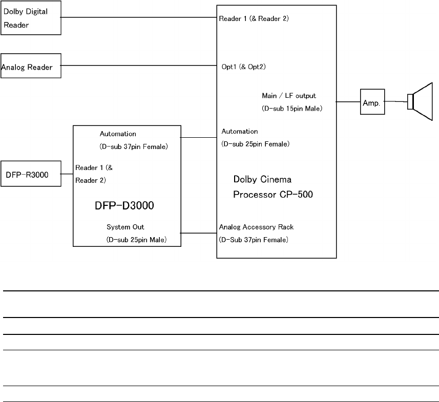
1. System configuration
2. Logic wiring connections
DFP-D3000 Automation I/O Connector CP-500 Automation Connector
(D-sub connector, 37 pin, Female) (D-sub connector, 25 pin, Female)
Pin No. Function Pin No. Function
Pin 16 Tally Common Pin 12 Signal Ground
Pin 32 SDDS Data OK Pin 6 SK6 Format Select Input (Note.)
- Wired to -
Pin 11 Preset 8 select
Pin 36 SDDS Data not OK Pin 4 SK4 Format Select Input (Note.)
n
These connections are valid only if the Dolby Digital format is assigned to SK4 and SDDS (User 1 or
higher) is assigned to SK 6 on the CP-500. On the DFP-D3000, SDDS must be assigned to Preset 8.