
Home Theater System User Manual
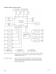
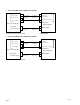
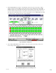
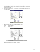
Table Of Contents
- Cover
- Table of Contents
- Check list
- 1. Introduction
- 2. Equipment and accessories
- 3. Basic checks of site and installation
- 4. Checks of correct DFP-R3000 Reader mounting
- 5. A-Chain alignment using DFP-D3000 front panel controls
- 6. B-Chain Alignment
- 7. Overall systems check and listening test
- 8. Troubleshooting
- 9. Appendix
- 9.1 DFP-D3000 Rear Panel Connector Pin Assignment
- 9.2 DFP-D3000 Input/Output Level
- 9.3 Changeover Settings
- 9.4 Settings for using DFP-D3000 as DFP-D2000
- 9.5 Description on Connection of DA-20 and DFP-D3000
- 9.6 Connecting the CP-500 and DFP-3000
- 9.7 Connecting the DTS-6, DTS-6D and DFP-D3000
- 9.8 Corresponding to DFP-D3000 Surround EX
- 9.8.1 Restrictions on Control of Surround EX Decoder
- 9.8.2 Connections of Audio System
- 9.8.3 Actual Connection of Control System
- 9.8.4 SA-10 Operations When Controlling from the DFP-D3000
- 9.8.5 Controlling Surround EX from DA-20
- 9.8.6 Controlling Surround EX from DTS-6 or DTS-6D
- 9.8.7 Controlling Surround EX control from Automation Controller
- 9.8.8 Adjustments of Audio System
- 9.9 Test Cable for Performing A-Chain Adjustment
- 9.10 Adjusting the Analog Track Pickup
- 9.10.1 Preliminary Preparations Before Adjustments
- 9.10.2 Lateral Film Guide Adjustment
- 9.10.3 Lateral Exciter Lamp Adjustment
- 9.10.4 Lateral Solar Cell Adjustment
- 9.10.5 Vertical Adjustment of Exciter Lamp
- 9.10.6 Slit Lens Adjustment
- 9.10.7 Double Checking of Illumination Inconsistency
- 9.10.8 Wiring Check
- 9.11 Description of the DFP-D3000 Setup Software Menus
- 9.11.1 Start-up Screen
- 9.11.2 Description of File Menu Items
- 9.11.3 Description of Config Menu Items
- 9.11.4 Description of Preset Menu Items
- 9.11.5 Description of A-Chain Menu Items
- 9.11.6 Description of Tools Menu Items
- 9.11.7 Description of Master Menu Items
- 9.11.8 Description of Test Menu Items
- 9.11.9 Description of Help Menu Items
9-43
DFP-3000
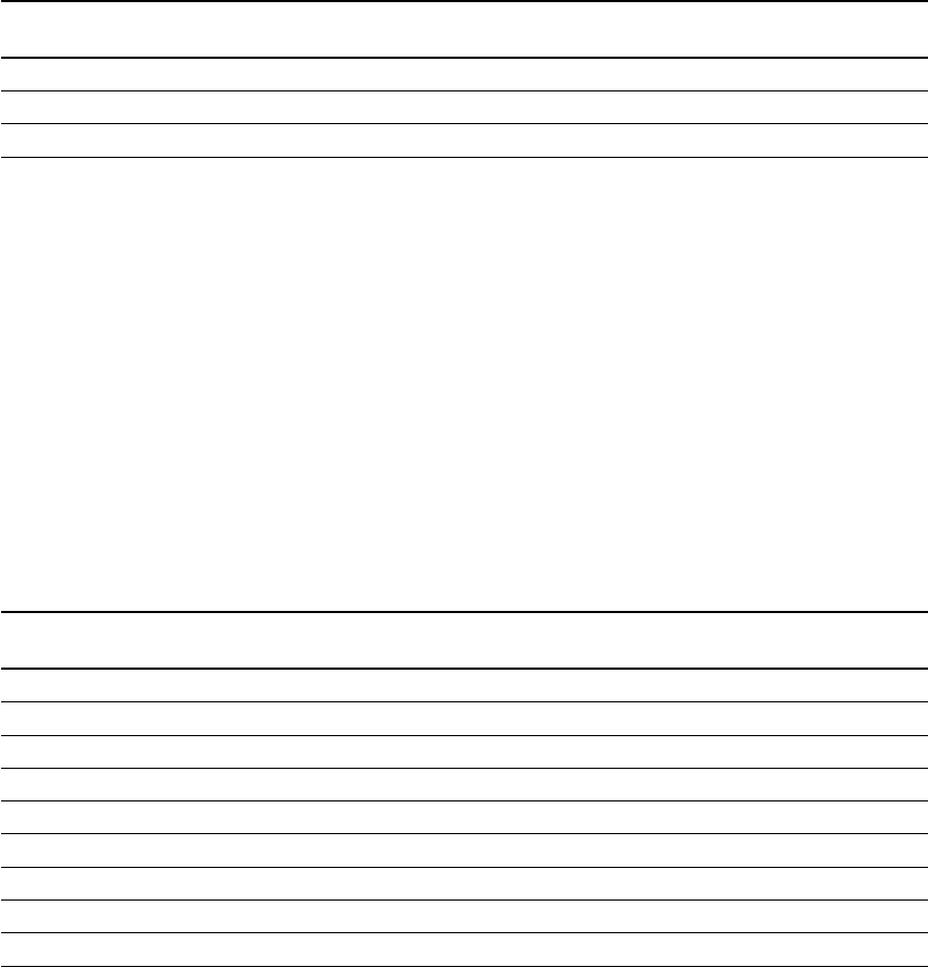
9.8.6 Controlling Surround EX from DTS-6 or DTS-6D
When using the DTS Co. DTS-6 or DTS-6D in the DFP-D3000 system, SA-10 operations can be con-
trolled from these cinema processors (DTS decoder) in the DFP-D3000 system.
In this case, connect the control cables of the DTS-6 or DTS-6D and SA-10 as follows. In this case, the
SA-10 can be controlled regardless of the DFP-D3000 control cables.
DTS-6 “to BS22” connector DTS-6D Automation connector SA-10 J3, Control Input
(IDC 10-pin Connector) (DB25 female) (DB25 female)
Pin 6: Relay Common Pin 13: Output common Pin 12: GND
Pin 9: out (N.O.) Pin 11: Logic SR Pin 2: CTRL 1, non-decode Mode
Pin 7: IN (N.O) Pin 25: Logic DTS Pin 5: CTRL 4, EX decode mode
The following cables are required other than the above for the DTS-6D system.
Connect Pin 6 “Force SR +” and Pin 9 “+5V Output” of the Automation connector.
Connect Pin 19 “Force SR _” and Pin 22 “5V GND” of the Automation connector.
9.8.7 Controlling Surround EX control from Automation Controller
When fallback using several digital formats is adopted in the DFP-D3000 system, or the SDDS signal
cannot be read, it is necessary to cancel the SA-10 Surround EX decoding operations as soon as possible.
It is also necessary to ensure compatibility for films not recorded with the Surround EX signal. By
changing the preset settings of the DFP-D3000, and preparing preset using the Surround EX not corre-
sponding to the SDDS input and preset not using the Surround EX (same as the Dolby Laboratories CP-
500), Surround EX can be controlled from an external Automation controller. The examples of preset
settings and connection methods of control cables are shown on the next page onwards. However when
using this connection method, set the Processor Select switch in the SA-10 to the CP-500 side.
DFP-D3000 Preset DFP-D3000 Automation SA-10, J3 Control Input
(37 pin, D-Sub, Female) (25 pin, D-sub, Female)
Preset 1: SDDS Pin 4: Preset 1 Pin 2: CTRL 1
Preset 2: Non-Sync Pin 5: Preset 2 Pin 3: CTRL 2
Preset 3: Mono (Pin 6: Ptrdry 3) No need No need to connect
Preset 4: NR1 Pin 7: Preset 4 Pin 4: CTRL 3
Preset 5: NR2 Pin 8: Preset 5 Pin 5: CTRL 4
Preset 6: AUX 1 Pin 9: Preset 6 Pin 6: CTRL 5
Preset 7: AUX 2 Pin 10: Preset 7 Pin 7: CTRL 6
Preset 8: SDDS EX Pin 11: Preset 8 Pin 8: CTRL 7
Pin 16: Tally Common Pin 12: GND