
Modem User Manual


LZT 123 1834 25
4 Mechanical Description
4.1 Interface Description
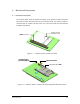
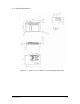
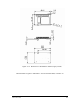
The pictures below show the mechanical design of the wireless modem along with
the positions of the different connectors and mounting holes. The wireless modem is
protected with tin coated steel ASI 1008/1010 covers that meet the environmental
and EMC requirements.
system connector
wireless modem
shielded circuits
system connector
wireless modem
shielded circuits
Figure 4.1-1 Wireless modem viewed from below
antenna connector
mounting hole &
ground connection
integrated SIM holder
antenna connector
mounting hole &
ground connection
integrated SIM holder
Figure 4.1-2 Wireless modem, viewed from above (Integrated SIM holder variant)