
Modem User Manual


LZT 123 1834 39
The module has approximately 40µF of internal capacitance across the
VCC pins. During initial power-up the host power supply will have to
charge this capacitance to the operating voltage. This initial in-rush
current may exceed the module’s normal peak current, sometimes
greater than an order of magnitude higher (depending upon the power
supply design) for a short duration (generally a few microseconds).
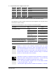
5.6 Voltage Reference (VREF)
Pin Name Direction Function
34 VREF Input (Output) Core voltage reference
GR64 provides a voltage reference interface for user applications.
Level shifters are integrated in the GR64 product. The integrated level shifters are
referenced to an internal IO regulator on the module side and to an application
voltage on the user side of the interface. There are two implementation of VREF,
dependent upon the users’ GR64 variant;
• VREF as an output (DPY 102 1494/10 & DPY 102 1494/30 variants)
• VREF as an input (DPY 102 1494/20 & DPY 102 1494/40 variants)
5.6.1 VREF as an Output
The version of GR64 without an integrated SIM holder provides a 2.8V reference to
the host side level shifter devices. This enables legacy users, and users of older
interface technology to connect directly to the GR64’s IO. The same reference
voltage is provided as an output on VREF. In this arrangement VREF can be used as a
further level shifter reference in the users application circuits, or to power external
circuits, since it has a 75mA current sourcing capability.
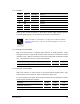
VREF output
Parameter Min Nom Max Unit
VREF output voltage 2.74 2.8 2.86 V
VREF load current 75 mA
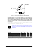
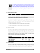
5.6.2 VREF as an Input
The version of GR64 with an integrated SIM holder provides a reference input to the
host side level shifter devices. This enables users of varying technologies to connect
directly to the GR64’s IO by providing a reference from their own application IO.
CAUTION