
Modem User Manual

LZT 123 1834 65
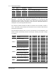
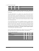
5.15 General Purpose IO
Pin Name Default Alternate function
21 GPIO1 GPIO1
22 GPIO2 GPIO2
23 GPIO3 GPIO3
24 GPIO4 GPIO4
13 GPIO5 ADIN4 ADC Input 4
33 GPIO6 LED LED control signal
32 GPIO7 DSR1 Data Set Ready (UART1)
36 GPIO8 RI Ring Indicator
39 GPIO9 RTS1 Ready To Send (UART1)
37 GPIO10 DTR1 Data Terminal Ready (UART1)
38 GPIO11 DCD1 Data Carrier Detect (UART1)
40 GPIO12 CTS1 Clear To Send (UART1)
All general purpose IO (GPIO) is programmable by the user. Some GPIO has alternate
functionality already associated with it; this is indicated in the default column. GPIO
which has alternate function is effectively multiplexed, so that the user chooses
through AT commands the appropriate configuration for their application.
GPIO is programmable for the following features:
• An input or output
• Level-sensitive or transition-sensitive
• Open drain or direct drive
• Polarity (inversion)
• Internal pull-up resistors
If pins labeled in the table above are not being used for the indicated alternative
function they may be used as general purpose inputs or outputs; they are not
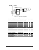
constrained to work in only one direction. All GPIO is level shifted on the GR64, and
has the characteristics defined in paragraph 5.3.1.
GPIO has a number of sharing (configuration) options. Sharing means that it is not
feasible to operate all the alternative features concurrently, however, with care,
dynamic switching from one feature to another is possible.
Users should note that if flow control is required for UART1 then GPIOs 7 to 12
inclusive cannot be configured for general purpose use.