PROFESSIONAL DISC CAMCORDER PDW-510/510P PDW-530/530P OPERATION MANUAL 1st Edition [English]
WARNING To prevent fire or shock hazard, do not expose the unit to rain or moisture. This label is located inside the outside panel of the unit. To avoid electrical shock, do not open the cabinet. Refer servicing to qualified personnel only. This Professional Disc Camcorder is classified as a CLASS 1 LASER PRODUCT. Laser diode properties Wavelength: 403 to 410 nm Emission duration: Continuous Laser output power: 65 mW (max. of pulse peak), 35 mW (max.
UTSÄTTAS FÖR OSYNLIG LASERSTRÅLNING, SOM ÖVERSKRIDER GRÄNSEN FÖR LASERKLASS 1. For the customers in the USA This equipment has been tested and found to comply with the limits for a Class B digital device, pursuant to Part 15 of the FCC Rules. These limits are designed to provide reasonable protection against harmful interference in a residential installation.
AVERTISSEMENT Afin d’éviter tout risque d’incendie ou d’électrocution, ne pas exposer cet appareil à la pluie ou à l’humidité. Afin d’écarter tout risque d’électrocution, garder le coffret fermé. Ne confier l’entretien de l’appareil qu’à un personnel qualifié. ATTENTION Comme le rayon laser utilisé dans ce Camescope de disques pour professionnels est dangereux pour les yeux, ne pas essayer de démonter le coffret. Faire effectuer l’entretien uniquement par un personnel qualifié.
Pour les clients européens Ce produit portant la marque CE est conforme à la Directive sur la compatibilité électromagnétique (EMC) (89/336/CEE) émise par la Commission de la Communauté européenne.
WARNUNG VORSICHT Um Feuergefahr und die Gefahr eines elektrischen Schlages zu vermeiden, darf das Gerät weder Regen noch Feuchtigkeit ausgesetzt werden. Um einen elektrischen Schlag zu vermeiden, darf das Gehäuse nicht geöffnet werden. Überlassen Sie Wartungsarbeiten stets nur qualifiziertem Fachpersonal. Die Laserstrahlung im Innern ist augenschädlich. Deshalb den Professional Disc Camcorder nicht öffnen/ zerlegen. Wartungsarbeiten ausschließlich qualifiziertem Fachpersonal überlassen.
ATTENZIONE CAUTELA Per evitare il pericolo di incendi o scosse elettriche, non esporre l’apparecchio alla pioggia o all’umidità. Per evitare scosse elettriche, non aprire l’apparecchio. Per le riparazioni, rivolgersi solo a personale qualificato. Poiché il raggio laser impiegato in questo camcorder di dischi professionale è dannoso alla vista, non tentare di smontare il rivestimento. Per la manutenzione rivolgersi esclusivamente a personale qualificato.
ADVERTENCIA CAUTION Para evitar el riesgo de incendios o electrocución, no exponga la unidad a la lluvia ni a la humedad. Para evitar descargas eléctricas, no abra el aparato. Solicite asistencia técnica únicamente a personal especializado. Como el rayo láser utilizado en este grabador de discos profesional es peligroso para los ojos, no trate de desarmar la caja. Solicite el servicio sólo al personal cualificado. CAUTION El uso de instrumentos ópticos con este producto aumentará el peligro a los ojos.
Table of Contents Chapter 1 Overview 1-1 Features ............................................. 15 1-1-1 Principal Differences Between the PDW-510/510P and PDW-530/530P15 1-1-2 Camera Features .............................. 15 1-1-3 Features of the Optical Disc Drive (VDR) .............................................. 16 1-1-4 Input and Outputs ............................ 17 1-1-5 Other Functions ............................... 17 1-2 Example of System Configuration .. 19 1-3 Precautions .................
5-6 Setting the Time Data ....................... 73 5-6-1 Setting the Time Code ..................... 73 5-6-2 Saving the Actual Time in the Time Code ................................................. 73 5-6-3 Setting the User Bits ........................ 73 5-6-4 Synchronizing the Time Code ......... 74 Chapter 6 Menu Displays and Detailed Settings 6-1 Menu Organization and Operation .. 77 6-1-1 Menu Organization .......................... 77 6-1-2 Displaying Menus............................
8-7 Attaching the Shoulder Strap ........ 125 8-8 Adjusting the Shoulder Pad Position.. 125 8-9 Putting on the Rain Cover (Not Supplied) ......................................... 126 8-10 Connecting the Remote Control Unit 127 Chapter 9 Maintenance 9-1 Testing the Camcorder Before Shooting 129 9-1-1 Preparations for Testing................. 129 9-1-2 Testing the Camera........................ 129 9-1-3 Testing the VDR............................ 130 9-2 Maintenance ....................................
Overview Recording format The PDW-510/510P/530/530P is a camcorder for ENG 1) and EFP 2), in which a color video camera using 2/3-inch high-definition CCDs of a 16:9 aspect ratio and a Professional Disc drive are combined integrally. The camera’s CCDs have approximately 1,000,000 picture elements (pixels) (the number of effective pixels: approximately 500,000).
Chapter 1 Overview • With the optional CBK-FC01 Pull Down Board installed, a 24 fps3) progressive scan video can be recorded subjected to pull-down, providing imaging quality close to that of film. (PDW-510/530 only) 1) Abbreviation of “Power Hole-Accumulated Diode.” “Power HAD” is a registered trademark of Sony Corporation. 2) More precisely, 29.97 fps 3) More precisely, 23.
Scene selection function Chapter 1 Overview The scene selection function allows you to select required clips only, and play them back in any order. 1) You can use PDZ-1 (logging software supplied with the PDW-1500, PDW-V1 and so on), or XPRI Meta Station (nonlinear editing software supplied with XDCAM support).
Furthermore, another control (the TURBO GAIN button) can also be used as an assignable switch. Chapter 1 Overview Alarm function If a fault is detected on the optical disc drive, or if the disc or battery capacity is low, this is notified by warning indicators and audible alarms. SMPTE (PDW-510/530)/EBU (PDW-510P/ 530P) color bars, and 1 kHz reference signal output Adjustment of a color monitor or external audio device is easy. Color bars for an SNG 1) uplink are also provided.
1-2 Example of System Configuration Viewfinder-related equipment Chapter 1 Overview The diagram below shows a typical configuration of the camcorder for ENG and EFP. For more information about the fittings, connections, or use of additional equipment and accessories, see Chapter 8 as well as the operation manuals for the connected equipment. AC power supply Name / Purpose Magnification Part No. Fog-proof filter – 1-547-341-11 Lens assembly –2.8 D to +2.0 D A-8262-537-A Lens assembly –3.
1-3 Precautions Chapter 1 Overview Use and Storage Do not subject the unit to severe shocks The internal mechanism may be damaged or the body warped. After use Always turn off the power. Before storing the unit for a long period Remove the battery pack. Use and storage locations Store in a level, ventilated place. Avoid using or storing the unit in the following places.
1-4 Using the CD-ROM Manual 1-4-1 CD-ROM System Requirements The following are required to access the supplied CDROM disc.
Chapter 1 Overview 22 1-4 Using the CD-ROM Manual
Locations and Functions of Parts and Controls Chapter 2 2-1 Power Supply 1 Battery attachment 2 DC IN connector 3 POWER switch 4 LIGHT switch a Battery attachment Attach a BP-IL75/GL95/M100 battery pack. Furthermore, by attaching an AC-DN2B AC Adaptor, you can operate the camcorder from AC power. Note If you mount other than the recommended battery pack in the camcorder, the operation may be unstable when starting or ending recording or playback.
2-2 Accessory Attachments 1 Shoulder strap posts 2 Light shoe Chapter 2 Locations and Functions of Parts and Controls 3 LIGHT connector 4 Lens mount 5 Lens locking lever 6 Lens mount cap 7 LENS connector 8 Tripod mount 9 Shoulder pad Lens cable clamp a Shoulder strap posts Attach the supplied shoulder strap to these posts. For details, see 8-7 “Attaching the Shoulder Strap” on page 125. b Light shoe Attach an optional accessory such as a video light to this shoe.
2-3 Audio Functions 8 Built-in speaker Chapter 2 Locations and Functions of Parts and Controls 1 Microphone 2 MIC IN connector 4 EARPHONE jack (rear) 7 ALARM volume control 3 MIC LEVEL control 6 MONITOR volume control 5 MONITOR switch and CH-1/2 / CH-3/4 switch 4 EARPHONE jack (front) Audio functions (1) a Microphone This is a super-cardioid directional monaural microphone with an external power supply (+48 V) system.
CH-1/2 CH-3/4 MONITOR Audio output switch switch position position CH-1/2 Chapter 2 Locations and Functions of Parts and Controls CH-3/4 CH-1 Audio channel 1 MIX Mix sound of channels 1 and 2 CH-2 Audio channel 2 CH-3 Audio channel 3 MIX Mix sound of channels 3 and 4 CH-4 Audio channel 4 Minimum Maximum ALARM volume control f MONITOR volume control This control adjusts the speaker or earphone volume for sounds other than the alarm sound. At the minimum position, no sound can be heard.
i LEVEL (CH-1/CH-2) (audio channel-1 and channel-2 recording level) controls These controls adjust the audio levels of channels 1 and 2 when the AUDIO SELECT switches are set to MANUAL. k AUDIO IN CH-1/CH-2 / CH-3/CH-4 (audio input selection) switches AUDIO IN CH-1/CH-2 switches These switches select the audio input signals to be recorded on audio channels 1 and 2. FRONT: The input signal source is the microphone connected to the MIC IN connector.
2-4 Shooting and Recording/Playback Functions 7 Viewfinder Chapter 2 Locations and Functions of Parts and Controls 8 Diopter adjustment ring Eyecup 1 Tally indicator 2 BRIGHT control 3 CONTRAST control 4 PEAKING control 5 ZEBRA switch 6 TALLY switch 0 Viewfinder left-right positioning ring qa Camera operator tally indicator 9 Viewfinder front-rear positioning lever qs Viewfinder stopper qd LOCK knob Shooting and recording/playback functions (1) a Tally indicator Setting the TALLY switch to HIGH or
g Viewfinder The viewfinder lets you view the image in black and white while shooting, recording or playing back. It also displays various warnings and messages related to the settings or operating conditions of the camcorder, a zebra pattern, safety zone marker 1), and center marker 2). For details, see 6-2-4 “Setting the Marker Display” on page 87. h Diopter adjustment ring Use this ring to adjust the viewfinder image for your vision.
Examples of shooting conditions and appropriate filters Shooting condition Filter Cloudy or raining 3 (5600 K) Very bright conditions such as snow, at 4 (5600 K + 1/ ND) 64 high altitudes, or at the seashore For the PDW-530/530P Chapter 2 Locations and Functions of Parts and Controls FILTER selector (outer knob) setting and CC filter selection FILTER selector (outer knob) setting CC filter selection A Cross filter 1) B 3200 K C 4300 K D 6300 K 1) A type of special effect filter.
switch and the FILTER selector. You can use the AUTO W/B BAL switch even when ATW 1) is in use. B (ATW): When this switch is set to B and on the FUNCTION 2 page of the OPERATION menu, “WHITE B CH” is set to “ATW” 1), ATW is activated. BARS, DCC OFF A color bar signal is output and the DCC circuit does not operate. For example, use the setting for the following purposes.
Chapter 2 Locations and Functions of Parts and Controls w VIDEO OUT connector (BNC type) This connector outputs a composite video signal for a video monitor. With a video monitor connected to this connector, you can monitor the picture being shot by the camera or the picture played back by the VDR. To choose between the composite video signal output and SDI signal output, use the menu.
Chapter 2 Locations and Functions of Parts and Controls wk REC START button wl VDR SAVE/STBY connector PLAY PRE V E /PAUS T NEX e; EJECT button and indicaor ea F REV button and indicator es PLAY/PAUSE button and indicator ed F FWD button and indicator ef NEXT button eg STOP button eh PREV button Shooting and recording/playback functions (4) wk REC START button Press this button to start recording. Press it again to stop recording.
eh PREV button This jumps to the beginning of the current clip, and pauses. During the jump, the F REV indicator flashes.Pressing this button together with the F REV button jumps to the first frame of the first clip recorded on the disc.
2-5 Output Video Operating Section 1 SEL/SET dial Chapter 2 Locations and Functions of Parts and Controls 2 THUMBNAIL button 3 Thumbnail indicator THUMBNAIL SEL/SET ESSENCE MARK 4 Sub clip indicator SUB CLIP 5 SUB CLIP button CLIP MENU PRESET 6 SHIFT button S.SEL REGEN CLOCK SHIFT F-RUN SET R-RUN Output video operating section a SEL/SET (select/set) dial When thumbnails (each representing a clip) are shown on the color LCD, you can select a particular thumbnail with this dial.
2-6 Menu Operating Section 2 STATUS ON/SEL / OFF switch Chapter 2 Locations and Functions of Parts and Controls 3 MENU ON/OFF switch MENU 4 CANCEL/PRST / ESCAPE switch 5 “Memory Stick” compartment Cover 1 MENU knob a MENU knob Use this knob to change the page selection or a setting within the menu. Press: If you press this knob when the arrow (b) is placed at the page title on the menu, the arrow changes to the question mark (?) and you can change the page.
e “Memory Stick” compartment “Memory Stick” Access indicator Label Chapter 2 Locations and Functions of Parts and Controls “Memory Stick” How to insert a “Memory Stick” Open the lid of the menu operating section, and insert a “Memory Stick” (not supplied), with the notch facing downward, in the direction shown by the arrow, so that it clicks into place. To remove a “Memory Stick”, first press it in to release the lock, then withdraw.
2-7 Time Code System Chapter 2 Locations and Functions of Parts and Controls 1 TC IN connector 2 TC OUT connector 3 GENLOCK IN connector Time code functions (1) a TC IN (time code input) connector (BNC type) To synchronize the time code with an external time code, input the reference time code to this connector.
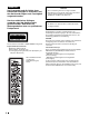
4 DISPLAY switch 5 RESET button 6 HOLD button THUMBNAIL SEL/SET 7 SEL/SET dial ESSENCE MARK SUB CLIP S.SEL 8 PRESET/REGEN/CLOCK switch REGEN CLOCK Chapter 2 Locations and Functions of Parts and Controls CLIP MENU PRESET SHIFT F-RUN SET R-RUN 9 F-RUN/SET/R-RUN switch Time code functions (2) d DISPLAY switch This cycles the data displayed in the counter display through the sequence TC, U-BIT, and COUNTER.
R-RUN: The time code value advances only during recording. Use this setting to have a consecutive time code on the disc. For details, see 5-6-3 “Setting the User Bits” on page 73 and 5-6-1 “Setting the Time Code” on page 73.
2-8 Warnings and Indications Besides the viewfinder, speaker and earphones, the indicators and displays described in this section also provide you with information such as the operating state of the camcorder and warnings.
e Back tally ON/OFF switch This switch enables or disables the back tally and rear tally indicators. ON: The back tally and rear tally indicators are enabled. OFF: The back tally and rear tally indicators are disabled. Chapter 2 Locations and Functions of Parts and Controls f Monochrome LCD This shows the remaining battery capacity, remaining disc capacity, time data, and so on. For details, see 2-9-1 “Monochrome LCD” on page 43.
2-9 Warnings and Indications on the LCDs 2-9-1 Monochrome LCD Time code display Chapter 2 Locations and Functions of Parts and Controls Disc status and battery status Disc status indicator Lights when the time code or real time is displayed. Full capacity is available. Time counter display: Shows the time code, user bits, and real time. Close to full state: “DISC” flashes. Full (disc must be replaced): “DISC” and “E” flash. Lights when the HOLD button is pressed.
2-9-2 Color LCD Disc status, battery status and audio level VDR operation status and status indicators Disc status indicator Chapter 2 Locations and Functions of Parts and Controls Full capacity is available. Close to full state: “DISC” flashes. Full (disc must be replaced): “DISC” and “E” flash. Formats of video and audio signals to be redorded. Audio level meters Warning display area This shows a message if a recording fault or condensation is detected.
Time code display Lights when VITC is selected for the time code. Lights in playback mode. Lights in non-drop frame mode. (PDW-510/530 only) Chapter 2 Locations and Functions of Parts and Controls Lights when the camcorder is synchronized with an external time code. Lights when the time code generator is on hold. Lights when the HOLD button is pressed 1) Lights when the time code or real time is displayed. Time counter display: Shows the time code, user bit data, and real time.
2-10 Indicators in the Viewfinder 1 TALLY indicator e Spare indicator This is a spare indicator. A menu operation makes it possible to use this as a REC indicator. Chapter 2 Locations and Functions of Parts and Controls 2 REC (recording) indicator 3 BATT (battery) indicator Viewfinder screen 4 (warning) indicator 5 Spare indicator 6 SAVE indicator Indicators on the viewfinder a TALLY indicator This indicator lights when the camcorder is in the Picture Cash mode.
Recording and Playback Chapter 3 3-1 Handling Discs 3-1-1 Discs Used for Recording and Playback This camcorder uses the following disc for recording and playback: PFD23 Professional Disc (capacity 23.3 GB) Note It is not possible to use the following discs for recording or playback: • Blu-ray Disc • Professional Disc for Data 3-1-2 Notes on Handling Handling The Professional Disc is housed in a cartridge, and is designed to allow handling free of risk from dust or fingerprints.
Note 3-1-4 Loading and Unloading a Disc To insert the disc correctly, make sure that the camcorder is in the upright position (the grip upside, the bottom downside). Loading a disc Proceed as follows. 1 Unloading a disc Turn on the POWER switch. With the power supply on, press the EJECT button to open the disc compartment lid and eject the disc. Then remove the disc. If you are not going to insert another disc, close the disc compartment lid.
You need not return the screw to its original position after taking out the disc. Turning on the power makes the disc compartment mechanism operable again. 3-1-5 Formatting a Disc Using a new disc An unused disc requires no formatting operation. The disc is automatically formatted so that it is ready to use when loaded into this unit. 3-2 Recording 3-2-1 Basic Procedures This section describes the basic procedures for shooting and recording.
• The battery indicator shows at least five segments. If it does not, replace the battery pack with a fully charged one. 4 5 For details of black balance adjustment, see 5-2-1 “Adjusting the Black Balance” on page 61. 2 Check that there are no obstructions such as cables near the disc compartment lid. Then press the EJECT button to open the disc compartment lid. When the black balance and white balance settings are already in memory: Set the WHITE BAL switch to A or B.
To play back the recorded clip Press the PREV button, then press the PLAY button to play from the beginning of the clip. 7 MAINTENANCE menu appears. If the menu has been used before, the last accessed page appears. 3 Repeat steps 5 and 6 as required for shooting. Each time you repeat steps 5 and 6 , successive clips are recorded on the disc. Clip 1 Clip 2 If the CONTENTS page is displayed, turn the MENU knob to move the b mark to “DISC”, and press the MENU knob to display the DISC page.
3-3 Checking the Recording – Playback PDW-510/510P/530/530P Color video monitor VIDEO IN connector 1) SDI IN connector 2) Chapter 3 Recording and Playback By pressing the PLAY/PAUSE button, you can review any length of recording on the viewfinder screen in black and white or in color on the color LCD. There are two other ways to review the recording. • Recording review: You can view the last 2 seconds of the recording on the viewfinder screen in black and white or in color on the color LCD.
The TOP menu appears. 3-4 Recording Video Signals from External Equipment 2 Turn the MENU knob to move the b mark to “OPERATION”. 3 Press the MENU knob. If this is the first time the OPERATION menu has been displayed, the CONTENTS page of the OPERATION menu appears. If the menu has been used before, the last accessed page appears. Notes • You can switch the signals to be recorded at any time while recording on the disc.
The b mark on the left of “REC VIDEO SOURCE” changes to a z mark and the z mark on the left of the setting changes to a ? mark. 6 Turn the MENU knob to display “EXT”. 21 SOURCE SEL REC VIDEO SOURCE: EXT REC CONTROL : I.LINK SBP2 MODE: TOP EXT OFF DSABL 2 Move the b mark to “EXT VIDEO SOURCE”, and press the MENU knob. 3 Turn the MENU knob to display “CMPST”. This ends the setting.
3-5 Freezing a Picture During Playback Viewing frozen pictures Proceed as follows. Press the PLAY/PAUSE button to start playback. 2 Press the PLAY/PAUSE button again at the instant when you want to freeze the picture. Chapter 3 Recording and Playback 1 A frozen picture appears. The time code is displayed in the counter display and the PLAY/PAUSE indicator flashes (one flash/ second). 3 To restart playback, press the PLAY/PAUSE button once again.
Chapter 3 Recording and Playback 56 3-5 Freezing a Picture During Playback
Thumbnail Search Chapter 4 This indicates that these are thumbnail images of clips. 4-1 Thumbnail Search Operations Sixth clip is selected from a total of 143 clips. Currently selected clip 4-1-1 Cuing Up to a Desired Clip To do this you display thumbnail images, then cue up to a desired clip. 2,3 1 Thumbnail indicator THUMBNAIL SEL/SET ESSENCE MARK SUB CLIP S.
Next, you can play the selected clip, or include it in a clip list, as required. To escape from the thumbnail images to full-screen display Press the THUMBNAIL button, turning off the thumbnail indicator. Note When operating from the battery, if the VDR SAVE/ STBY switch is in the SAVE position, there is a delay until the thumbnail display appears. During this delay, the indication “THUMBNAIL PROCESSING” appears on the viewfinder screen and color LCD.
Adjustments and Settings for Recording 5-1 Setting the Recording Format (PDW-530/530P only) Before recording with the PDW-530/530P, it is necessary to set the recording format for each of video and audio. Video recording format: MPEG IMX 50 Mbps, 40 Mbps, 30 Mbps, or DVCAM Audio recording format: 16-bit 48 kHz or 24-bit 48 kHz Chapter 5 USER USER MENU CUSTOMIZE ALL OPERATION PAINT MAINTENANCE FILE DIAGNOSIS 3 Turn the MENU knob to move the b mark to “MAINTENANCE”.
M09 VDR MODE REC TALLY BLINK REC START/STOP MODE SELECT TIMER SET REC FORMAT 6 : : : : : ON OFF SEL IH IMX50 REC TALLY BLINK REC START/STOP MODE SELECT TIMER SET REC FORMAT Chapter 5 Adjustments and Settings for Recording Turn the MENU knob to display the desired recording format. M09 VDR MODE REC TALLY BLINK REC START/STOP MODE SELECT TIMER SET REC FORMAT TOP : ON : OFF : SEL : IH :? IMX40 Press the MENU knob. This confirms the selection.
5-2 Adjusting the Black Balance and the White Balance For details of manual black balance adjustment, refer to the Maintenance Manual. To adjust the black balance, proceed as follows. To ensure excellent image quality when using this camcorder, conditions may require that both the black balance and the white balance be adjusted. OUTPUT/DCC switch Black balance adjustment 1 Set the OUTPUT/DCC switch to CAM. 2 Push the AUTO W/B BAL switch to BLK and release the switch.
Black balance adjustment error messages Error message Meaning ABB : NG IRIS NOT CLOSED The lens iris did not close; adjustment was impossible. ABB : NG TIME LIMIT Adjustment could not be completed within the standard number of attempts. ABB : NG R (or G or B) : OVERFLOW The difference between the reference value and the current value is so great that it exceeds the range. Adjustment was impossible.
FILTER selector (inner knob) setting and ND filter selection FILTER selector (inner knob) ND filter setting 4 1 /64 ND For the PDW-510/510P: AUTO W/B BAL switch FILTER selector setting and filter selection FILTER selector setting Filter selection 1 3200 K 2 5600 K + 1/8 ND 3 5600 K 4 5600 K + 1/64 ND If the setting of the FILTER selector is changed, a message reporting the setting appears for about 3 seconds in the setting change and adjustment progress message display area of the viewfinder
Error message Meaning If a memory error occurs WHITE : NG COLOR TEMP HIGH The color temperature is too high. Select a suitable filter setting. WHITE : NG COLOR TEMP LOW The color temperature is too low. Select a suitable filter setting. WHITE : NG TIME LIMIT Adjustment could not be completed within the standard number of attempts. WHITE : NG POOR WHITE AREA The white area could not be checked.
5-3 Setting the Electronic Shutter This section describes the shutter modes that can be used with the electronic shutter of the camcorder, and describes the procedure for selecting the shutter speed and shutter mode. 5-3-1 Shutter Modes The shutter modes that can be used with the electronic shutter and the shutter speeds that can be selected are listed below. the red, green, and blue intensities are actually changing in synchronization with the frequency of the power supply causing flicker.
1 2 Setting the shutter speed in ECS (Extended Clear Scan) mode 1 Set the shutter speed mode to ECS. SHUTTER selector For the operation, see the previous item “Setting the shutter mode and standard-mode shutter speed”. Chapter 5 Adjustments and Settings for Recording The current shutter setting indication appears for about 3 seconds in the setting change and adjustment progress message display area of the viewfinder screen. Examples: “: SS : 1/250”, “: SLS : 8FRAME”, “: ECS : 60.0 Hz” 3 ECS:60.
For the operation, see “Setting the shutter mode and standard-mode shutter speed” on page 65. SLS: 1 FRAME Example of viewfinder screen display for SLS setting operation 2 2 Turn the MENU knob to move the b mark to OPERATION. 3 Press the MENU knob. If this is the first time the OPERATION menu has been displayed, the CONTENTS page of the OPERATION menu appears. If the menu has been used before, the last accessed page appears.
7 To end the menu operation, set the MENU ON/OFF switch to OFF or close the cover of the menu operating section. The menu disappears from the screen and the display indicating the current status of the camcorder appears along the top and bottom of the screen. 5-4 Changing the Reference Value for Automatic Iris Adjustment The reference value for automatic iris adjustment can be changed to aid the shooting of clear pictures of back-lit subjects, or to prevent blown-out highlights.
The z mark on the left of the selected item changes to a b mark and the ? mark on the left of the setting changes to a z mark. The IRIS OVERRIDE item is set to “ON”. 5 Set the MENU ON/OFF switch to OFF or close the cover of the menu operating section. The AUTO IRIS page disappears from the screen. Opening the lens iris 6 Turn the MENU knob to change the reference value. Iris opened by 1 stop (two bars) Note Iris opened by 0.
The b mark on the left of the selected item changes to a z mark and the z mark on the left of the setting changes to a ? mark. 5 Turn the MENU knob until the desired auto iris window appears, then press the MENU knob. 5-5 Adjusting the Audio Level Setting the AUDIO SELECT CH-1/CH-2 switches to AUTO automatically adjusts the input levels of the audio signal to be recorded in audio channels 1 and 2. You can also adjust the audio level manually.
1 To adjust the signal input to the AUDIO IN CH1 or AUDIO IN CH2 connector, set the AUDIO IN CH-1 or AUDIO IN CH-2 switch to REAR. To adjust both input signals, set both switches to REAR. 2 Set the AUDIO SELECT switch(es) corresponding to the channel(s) selected in step 1 to MANUAL. 3 With the LEVEL control for the channel selected in step 1, adjust so that the audio level meter shows up to –20 dB for a normal input volume.
• The second top bar may turn on occasionally, but do not allow the top bar to go on. If it goes on, the audio level is too high. Correspondence between recording level adjustments and audio level controls In the AUDIO-3 page of the MAINTENANCE menu, you can select which audio level control controls the audio recording level of the front microphone input. The correspondence between the controls and the menu items and settings is as follows. F: The audio signal from the front microphone is recorded.
F-RUN: Free run. The time code generator keeps running, regardless of the operating state of the VDR. R-RUN: Recording run. The time code generator runs only while recording. 5-6 Setting the Time Data 5-6-1 Setting the Time Code The time code setting range is from 00 : 00 : 00 : 00 to 23 : 59 : 59 : 29 (hours : minutes : seconds : frames) for the PDW-510/530, and from 00 : 00 : 00 : 00 to 23 : 59 : 59 : 24 for the PDW-510P/530P. To set the time code, proceed as follows.
regeneration of an external time code. You can also synchronize the time code generators of other camcorders/ VTRs with the internal generator of this camcorder. Connections for time code synchronization Connect both the reference video signal and the external time code as illustrated below. 1 RESET button Example 1: Synchronizing with an external time code THUMBNAIL SEL/SET 3 ESSENCE MARK SUB CLIP S.
time code cannot be synchronized with the reference video signal. In this case, set the GENLOCK ON/OFF item to “ON” on the GENLOCK page of the MAINTENANCE menu. 4 1 3 2 User bit settings during time code synchronization When the time code is synchronized, only the time data is synchronized with the external time code value. Therefore, the user bits can have their own settings for each camcorder. You can also synchronize the user bits with external user bit data.
Chapter 5 Adjustments and Settings for Recording 5-6 Setting the Time Data 76
Menu Displays and Detailed Settings 6-1 Menu Organization and Operation 6-1-1 Menu Organization The following shows the organization of menus that you can use to make various settings and adjustments. Chapter 6 For details of customizing the USER menu, see 6-1-4 “Editing the USER Menu” on page 80. TOP menu The TOP menu consists of the following submenus.
• OPERATION menu: This menu contains items for changing settings according to conditions related to the subject when the camcorder is being operated. • PAINT menu This menu contains items for making detailed image adjustments while using a waveform monitor to monitor the waveforms output by the camera. Support of a video engineer is usually required to use this menu.
Returning to the TOP menu from other menus There are two methods. • Align the b mark with “TOP” at the top right of the menu page, and press the MENU knob. • Push the CANCEL/PRST / ESCAPE switch down to the ESCAPE position repeatedly until the TOP menu appears. 2 Press the MENU knob. The selected page is displayed. Go to step 4. 2 Turn the MENU knob until the desired page appears. 3 Press the MENU knob. A b mark appears on the left of the item currently selected on the page.
The z mark on the left of the selected item changes to a b mark and the ? mark on the left of the setting changes to a z mark. The setting is confirmed. 8 To continue setting other items in the same page, repeat steps from 4 to 7. To cancel a change or return to the standard settings Proceed as follows. 1 2 Before pressing the MENU button in step 7 of the above procedure, push the CANCEL/PRST / ESCAPE switch up to the CANCEL/PRST position. Under the page name, a message “CANCEL DATA OK?” appears.
If the USER MENU CUSTOMIZE menu has been used before, the last accessed page appears. 3 If the CONTENTS page is displayed, turn the MENU knob to move the b mark to one of USER 1 EDIT to USER 19 EDIT and ASSIGN SEL EDIT, then press the MENU knob to display the page. The USER P2 EDIT page appears again, displaying the newly added item. 7 Add the remaining items by repeating steps 4 to 6. You can add up to 10 items on one page.
3 Turn the MENU knob to move the b mark to the position where you want to move the item, then press the MENU knob. E02 USER 1 EDIT 3 If a different page is displayed, turn the MENU knob until the EDIT PAGE screen appears, then press the MENU knob to select the page. TOP WHITECH : AWB TEST OUT MENU : OFF OFFSET WHITE : WARM COOL : COLOR FINE : MASTER BLACK : OFF 3200 0 0 The item selected in step 1 moves to the position that you selected in step 3.
1 2 Open the EDIT PAGE of the USER MENU CUSTOMIZE menu. Turn the MENU knob to move the b mark to the page to be deleted. E01 EDIT PAGE PUSH TO PAGE INSERT 01.OUTPUT 02.TEST OUT 03.FUNCTION 1 04.VF DISP 1 05.'!'LED 06.MARKER 1 07.GAIN SW 08.VF SETTING 09.AUTO IRIS Push the CANCEL/PRST / ESCAPE switch to CANCEL/PRST. The message “PRESET DATA OK?” appears. E01 EDIT PAGE DELETE PAGE OK ? 01.OUTPUT 02.TEST OUT 03.FUNCTION 1 04.VF DISP 1 05.VF DISP 2 06.'!'LED 07.MARKER 1 08.GAIN SW 09.VF SETTING 10.
6-2 Status Display on the Viewfinder Screen The viewfinder screen displays not only the video picture but also characters and messages indicating the camcorder settings and operating status, a center marker, a safety zone marker, etc. When the MENU ON/OFF switch is set to OFF and the DISPLAY switch is set to ON, the items for which an “ON” setting was made in the VF DISP1 page of the USER menu or with related switches are displayed at the top and bottom of the screen.
i Iris setting/auto iris override This indicates the f-stop (iris setting) of the lens. Also, the auto iris override is displayed using bars which appear in the upper and lower parts to the left of the F number respectively. For details, see “Changing the reference value” on page 68. j Remaining disc capacity This indicator indicates the remaining disc recording time (in minutes) of the VDR. m Gain This indicates the gain of the video amplifier, as set by the GAIN selector.
To select the items to be displayed on the viewfinder screen, proceed as follows. 2) For detailed information on the display mode, see 6-2-3 “Display Modes and Setting Change Confirmation/Adjustment Progress Messages” on page 87. VF DISP 2 page Item CANCEL/PRST / ESCAPE switch MENU knob 1 MENU ON/OFF switch 2 DISP ZOOM Zoom position indicator DISP COLOR TEMP. Displays the color temperature.
2 6-2-3 Display Modes and Setting Change Confirmation/ Adjustment Progress Messages The b mark on the left of “VF DISPLAY MODE” changes to a z mark and the z mark on the left of the setting changes to a ? mark. You can limit or suppress the messages that give details of setting changes and adjustment progress and results by setting a display mode.
Item Description CENTER To display the center marker, set to ON. SAFETY ZONE To display the safety zone, set to ON. SAFETY AREA To select the safety zone range (80%, 90%, 92.5 % or 95 %), when SAFETY ZONE is set to ON. ASPECT To display the aspect marker, set to ON. ASPECT SELECT To select the type of the aspect marker. ASPECT MASK (4:3)1) To make the areas out of the selected aspect marker dimmer, set to ON.
The b mark on the left of the selected item changes to a z mark and the z mark on the left of the setting changes to a ? mark. 4 U12 SHOT DISP SHOT SHOT SHOT SHOT SHOT SHOT SHOT Turn the MENU knob to change the setting, and press the MENU knob. The z mark on the left of the selected item changes to a b mark and the ? mark on the left of the setting changes to a z mark. 5 To continue setting other items, repeat steps 3 and 4.
A x mark appears over the first character position in the string, and characters can now be input. The items selected for superimposed recording appear on the screen and are recorded superimposed on the color bars. U11 SHOT ID ID-1 ID-2 ID-3 ID-4 6-2-7 Setting the Shot ID On the SHOT ID page of the USER menu, you can set a shot ID of up to 12 alphanumeric characters, spaces, and symbols. When the OUTPUT/DCC switch is set to BARS, DCC OFF, this shot ID is output with the color bar signal.
1 In step 4 above, move the x mark over “INS”, and press the MENU knob. U11 SHOT ID ID-1 ID-2 ID-3 ID-4 Move the x mark over “INS”. 2 : : : : TOP CM015 ssssssssssss ssssssssssss ssssssssssss ABNORMAL window ABNORMAL xxxxxxxxxxxxxxxxxxxxxxxxx !GAIN : ON 3dB !SHUTTER : ON OFF WHT PRESET : ON W:P ATW RUN : ON OFF EXTENDER : ON OFF !FILTER : OFF 1B OVERRIDE : ON OFF $%&'()*+,-.
OFF switch is set to OFF (when the cover of the menu operating section is closed, OFF is automatically selected). 3 Turn the MENU knob to move the b mark to the item you want to set, and press MENU knob. The b mark on the left of the selected item changes to a z mark and the z mark on the left of the setting changes to a ? mark. 4 By pushing the STATUS ON/SEL / OFF switch up to ON/SEL, the confirmation window appears. Each time you push this switch up to ON/SEL, the window switches.
M15 MAINTENANCE GENLOCK RETURN VIDEO 4 TOP : : ON OFF GL H PHASE : GL SC PHASE : GL SC 0/180 SEL : 0 0 180 However, the image is switched while you are holding down the ASSIGN 1/3/4 switch to which the return video function is assigned, even if no signal is input to the GENLOCK IN connector. Carry out setting operations as follows. 1 Turn the MENU knob to move the b mark to “GENLOCK”, and press the MENU knob.
3 6-3 Adjustments and Settings from Menus The camcorder provides menus for adjustments and settings. The b mark on the left of the selected item changes to a z mark and the z mark on the left of the setting changes to a ? mark. 4 Turn the MENU knob to change the setting, and press the MENU knob. 6-3-1 Setting Gain Values for the GAIN Selector Positions The z mark on the left of the selected item changes to a b mark and the ? mark on the left of the setting changes to a z mark.
Item Description LCD BRIGHT Adjusts the LCD brightness when the LCD switch is in the L position. 3 If a different page is displayed, turn the MENU knob until the WHITE page appears, and press the MENU knob to select the page. LCD BRIGHT Adjusts the LCD brightness when the LCD switch is in the H position. LCD COLOR Adjusts the color saturation of the LCD. i.LINK SBP2 MODE Selects whether or not to use the i.LINK connector SBP2 interface.
6-3-4 Specifying an Offset for the Auto White Balance Setting By setting an offset for the value of auto white balance, you can make the picture warmer or colder. The OFFSET WHT page of the OPERATION menu allows you to do this setting. Proceed as follows. 1 Holding down the MENU knob, move the MENU ON/ OFF switch from OFF to ON. Item Description WARM-COOL Sets the offset for the white balance of channel B, using the color temperature.
U03 FUNCTION1 ASSIGN SW <1> ASSIGN SW <2> ASSIGN SW <3> ASSIGN SW <4> TURBO SW DF/NDF CACHE/INTVAL TOP : : : : : : : ATW OFF OFF OFF TURBO DF OFF Description ATW Assigns the ON/OFF function of autotracing white balance. RETURN VIDEO Assigns the ON/OFF function to display the image of the return video signal on the viewfinder to the switch.2) Assigns the same function as that of the RET switch on the lens to the switch. REC SWITCH Assigns the VTR S/S (start/stop) function to the switch.
Function Content REC VIDEO SOURCE 2) Selects which signals you will record pictures being shot by the camcorder or video signals from external equipment connected to GENLOCK IN connector. UA01 to UA10 3) Assigns the items assigned in the ASSIGN SEL menu. 1) Even when the MARKER item is set to “OFF” on the MARKER page of the USER menu, the ASSIGN 2 switch allows you to display or not to display all markers.
Item Description MONTH Sets the month. DAY 5 3 Turn the MENU knob to display the desired value, and press the MENU knob. 7 To continue the remaining settings, repeat steps 5 and 6. 8 When you finish settings, turn the MENU knob to move the b mark to “OK”, then press the MENU knob. To cancel the setting Before executing step 8, move the b mark to “ESC” at the top right of the window and press the MENU knob. Alternatively, push the CANCEL/PRST / ESCAPE switch down to the ESCAPE side.
The b mark on the left of the selected item changes to a z mark and the z mark on the left of the setting changes to a ? mark. 3 Turn the MENU knob to display the desired aspect ratio, and press the MENU knob. The z mark changes to a b mark and the ? mark on the left of the aspect ratio changes to a z mark. 4 To end the menu operation, set the MENU ON/OFF switch to OFF or close the cover of the menu operating section.
Setting the CCD scan mode to the progressive scan mode The scan mode of the camcorder has been set to the interlace scan mode at the factory. The FORMAT page of the OPERATION menu allows you to change the CCD scan mode to the progressive scan mode. 1 Follow the procedures given in steps 1 to 3 described in 6-3-4 “Specifying an Offset for the Auto White Balance Setting” on page 96, to display the FORMAT page of the OPERATION menu.
Chapter 6 Menu Displays and Detailed Settings 102 6-4 Resetting USER Menu Settings to the Standard Settings
Saving and Loading User Setting Data 7-1 Saving and Loading User Files to and from a “Memory Stick” The camcorder is equipped with a “Memory Stick” drive, which enables you to save user files, scene files, lens files, reference files and “ALL” files. You can load these files from the “Memory Stick” for immediate recall of a particular setting configuration.
Removing the “Memory Stick” Check that the access indicator is not lit, then gently press in the “Memory Stick” and release. It pops out, and you can withdraw it from the slot. • When storing and carrying the “Memory Stick”, keep it in its original case to ensure protection of important data. • When carrying the camcorder with the “Memory Stick” inserted, close the cover of the menu operating section. • Avoid removing the “Memory Stick” from the insertion slot while the access indicator is lit.
When a ? appears on the left of “P00” at the top left of the page, you can change the page. Up to 20 pages, from P00 to P19, can be used to save user files in the “Memory Stick”. Each page can hold up to 5 files. 4 P00 USER SAVE 001.NEW 002.NEW 003.NEW 004.NEW 005.NEW The menu disappears from the viewfinder screen, and the display indicating the current status of the camcorder appears along the top and bottom of the screen.
2 U16 USER FILE USER FILE LOAD USER FILE SAVE TOP : : EXEC EXEC Turn the MENU knob to move the b mark until the desired type of the display contents (see the following table) appears, then press the MENU knob. F.ID : sssssssssssssssss USER PRESET : EXEC P00 USER LOAD DISPLAY MODE 2 ESC : F.ID 001.USER1 002.USER2 003.NO FILE 004.USER4 005.USER5 Press the MENU knob. A character table appears, allowing you to select characters you want to enter.
P00 USER LOAD DISPLAY MODE 001.USER1 002.USER2 003.NO FILE 004.USER4 005.USER5 5 ESC : ALL JAN/01/04 JAN/15/04 FEB/05/04 FEB/20/04 Turn the MENU knob to move the b mark to the desired file number to be loaded, and press the MENU knob. The message “LOAD OK? YES b NO” appears and the access indicator lights. P00 USER LOAD ESC LOAD OK? YES NO DISPLAY MODE : ALL 001.USER1 002.USER2 003.NO FILE 004.USER4 005.
If you want to set a file ID for the data to be saved Set the file ID before going to step 3. P01 SCENE STORE DISPLAY MODE For details on setting the file ID, see “Setting the file ID” on page 109. 3 001.SCENE1 002.STANDARD 003.STANDARD 004.STANDARD 005.STANDARD Turn the MENU knob to move the b mark to “SCENE STORE”, and press the MENU knob. F04 SCENE FILE P01 SCENE STORE ESC STORE OK? YES NO DISPLAY MODE : ALL EXEC EXEC 001.SCENE1 002.STANDARD 003.STANDARD 004.STANDARD 005.
When SCENE WHITE DATA is set to ON The white balance setting data selected when you save the scene file is saved. For example, when the WHITE BAL switch is set to A, the adjusted values in memory A are saved in the scene file, and when the WHITE BAL switch is set to PRST, the preset value is saved. When SCENE WHITE DATA is set to OFF White balance setting data is not stored in the scene file.
04 SCENE FILE The camcorder returns to the settings before selecting this scene file. TOP s1 :STANDARD s2 :STANDARD s3 :STANDARD s4 :STANDARD s5 :STANDARD sSTANDARD SCENE RECALL SCENE STORE F.ID: SCENE21 To load a scene file saved in the “Memory Stick” Proceed as follows. : : EXEC EXEC 1 On the SCENE FILE page, turn the MENU knob to move the b mark to “SCENE RECALL”, and press the MENU knob. Carry out the procedure from step 3 in 7-2-1 “Saving a Scene File” on page 107.
Loading scene files from a “Memory Stick” into the camcorder memory You can load up to five scene files stored in the “Memory Stick” into the camcorder memory in a single operation. 1 After displaying the SCENE FILE page (see page 109), turn the MENU knob to move the b mark to “SCENE RECALL”, and press the MENU knob.
7-3 Jumping to a FileRelated Menu Page When Inserting a “Memory Stick” A “Memory Stick” enables you to save user files, scene files, lens files, reference files and “ALL” files. The camcorder menu system allows you to make a setting so that when a “Memory Stick” holding these files is inserted while in menu operating mode, a menu page relating to the desired file is automatically displayed on the screen. Thus you can proceed to file operation quickly.
Setting Up the Camcorder 8-1 Power Supply Chapter 8 Attaching the battery pack 1 The following power supplies can be used with the camcorder. • BP-IL75/GL95 Lithium-ion Battery Pack • BP-M100 Nickel Metal Hydride Rechargeable Battery Pack • AC power using the AC-550/550CE or AC-DN2B AC adaptor Press the battery pack against the back of the camcorder, aligning the line on the side of the battery pack with the matching line on the camcorder. Back of camcorder BP-IL75/GL95/ M100 Align these lines.
Detaching the battery pack 8-1-3 Using an AC Adaptor ACCESS indicator Holding the button in, pull the battery pack up. Using the AC-550/550CE AC adaptor Connect the camcorder to the AC power supply through the AC-550/550CE AC Adaptor as shown in the following figure, and turn the POWER switch of the AC-550/550CE on.
2 8-2 Adjusting the Viewfinder Slide the viewfinder longitudinally to the most convenient position. 3 Tighten the viewfinder front-rear positioning lever and the LOCK knob. For maximum viewing convenience, you can adjust the viewfinder position in the left-right and backward-forward directions. 8-2-2 Adjusting the Viewfinder Focus and Screen 8-2-1 Adjusting the Viewfinder Position Adjusting the viewfinder focus Turn the diopter adjustment ring until the viewfinder image is sharpest.
8-2-3 Detaching the Viewfinder Viewfinder stopper 8-2-4 Moving the viewfinder shoe up 1 Using a hexagonal wrench 2.5 mm across flats, remove the bolts (M3 × 25) and spring washers, to detach the viewfinder shoe from the camcorder body. Viewfinder shoe assembly (A-8278-412-G) Detaching the viewfinder 1 Point the viewfinder barrel up or down. 2 Loosen the viewfinder left-right positioning ring.
8-2-5 Using the BKW-401 Viewfinder Rotation Bracket 3 Using a hexagonal wrench 2.5 mm across flats, detach the viewfinder shoe from the camcorder body. 4 Using the two bolts (M3 × 10) and washers removed in step 2, attach the rotation mechanism assembly of the BKW-401 to the camcorder. By fitting a BKW-401 Viewfinder Rotation Bracket (not supplied), you can rotate the viewfinder out of the way so that your right leg does not hit the viewfinder while you are carrying the camcorder.
8-3 Mounting the Lens To mount the lens, proceed as follows. For information about using the lens, refer to the lens manual. Reattaching the eyepiece 1 Align the red marks on the eyepiece locking ring and the viewfinder barrel. 2 Align the red mark on the end of the eyepiece end with the red marks on the eyepiece locking ring and the viewfinder barrel. Then insert the eyepiece into the viewfinder barrel.
8-4 Adjusting the Flange Focal Length If the lens does not stay in focus properly as you zoom from telephoto to wide angle, adjust the flange focal length (the distance from the plane of the lens mounting flange to the imaging plane). Make this adjustment after mounting or changing the lens. Adjusting the flange focal length The position of the controls for adjusting the flange focal length vary somewhat from lens to lens. Check the identification of the various controls in the lens manual.
2 Place the microphone in the microphone holder. Tighten the screw. Place the microphone in the holder so that “UP” is at the top. +48V/OFF switch Monaural microphone Close the microphone holder. AUDIO IN CH-1/CH-2 switches AUDIO IN CH1 or CH2 connector Using an external microphone (not attached to the camcorder) 3 Plug the microphone cable into the MIC IN connector, then set the AUDIO IN switch for the desired recording channel to FRONT or F. Connect to the MIC IN connector.
Note When you detach the CAC-12 Microphone Holder once you have attached to the camcorder, be careful not to lose the two screws fixing the CAC-12. After detaching the CAC-12, be sure to put the two screws back into their original places (see the figure illustrating the step 1 operation). Screws removed in step 1 CAC-12 3 Open the CAC-12 and remove the microphone adaptor. Open the CAC-12.
For details about attaching the BP-IL75/GL95/M100 Battery Pack, see 8-1-1 “Using a Battery Pack” on page 113. WRR-855A/ 855B BP-IL75/GL95/M100 Set the AUDIO IN switch (see page 120) to WIRELESS for the channel to be used. Adjustment screws Mount plate (supplied with WRR-862) For the operation of the WRR-855A/855B, refer to the manual supplied with the WRR-855A/855B.
LINE/AES/EBU/ MIC switch LINE / AES/EBU / MIC switch Audio equipment AUDIO IN CH-1/CH-2 switches to AUDIO IN CH1 or to DC OUT connector CH2 connector AUDIO IN CH-1/CH-2 switches to AUDIO IN CH1 or CH2 Line input connection 8-5-4 Connecting Line Input Audio Equipment Connect the audio output connector of the audio equipment that supplies the line input signal to the AUDIO IN CH1 or CH2 connector.
8-6 Tripod Mounting You can easily mount and dismount the camcorder on a tripod by using the VCT-14 tripod adaptor (not supplied). 1 Attach the tripod adaptor to the tripod. Note The tripod adaptor pin may remain in the engaged position even after the camcorder is removed. If this happens, press the red button against the lever a second time and move the lever as shown below until the pin returns to the stowed position.
8-7 Attaching the Shoulder Strap 8-8 Adjusting the Shoulder Pad Position Attach the supplied shoulder strap as shown below. You can shift the shoulder pad from its center position (factory setting) backward by up to 10 mm (3/8 inch) or forward by up to 25 mm (1 inch). This adjustment helps you get the best balance for shooting with the camcorder on your shoulder.
8-9 Putting on the Rain Cover (Not Supplied) Attach the rain cover (part number 3-191-064-02) as illustrated below. You can insert and remove cassette tapes, operate various switches and controls, and mount the camcorder on the tripod adaptor with the rain cover attached. When a shoulder belt is not used, cover the holes on the rain cover with caps. Insert the viewfinder barrel here with the eyecup out and fasten the drawstring around the eyecup. When you use a shoulder strap, use these holes.
8-10 Connecting the Remote Control Unit Connecting the RM-B150/B750 Remote Control Unit (not supplied) enables remote control of the principal camera functions. Connecting the remote control unit to the REMOTE connector (8-pin) automatically puts the camcorder into remote control mode. If you disconnect the remote control unit, the remote control mode is canceled.
Structure of the paint adjustment data Non-volatile memory Setup menu of the camcorder RMB150 Independent data region MASTER BLACK MASTER GAMMA KNEE POINT DETAIL LEVEL R/B GAIN R/B BLACK Remote control data region MASTER BLACK MASTER GAMMA KNEE POINT DETAIL LEVEL R/B GAIN R/B BLACK Hardware of the camera For details, refer to the operation manual supplied with the remote control unit.
Maintenance 4 9-1 Testing the Camcorder Before Shooting Check the functions of the camcorder before setting out for a shooting session, preferably by operating the camcorder together with a color video monitor. 9-1-1 Preparations for Testing 3 4 1 2 Chapter 9 After confirming that the disc is not write-protected, load the disc and close the disc compartment lid.
Testing the viewfinder 1 Adjust the position of the viewfinder. 2 Check that the color bars are displayed on the viewfinder screen, and adjust the BRIGHT, CONTRAST, and PEAKING controls to give the best color bar display. 3 5 Set the OUTPUT/DCC switch to CAM, and change the FILTER selector position in the sequence of 1, 2, 3 and 4. Check that the FILTER indicator on the viewfinder screen displays the correct numbers.
(1) Testing the recording and playback functions 2 Set the AUDIO SELECT CH-1/CH-2 switches to AUTO. 1 3 Set the AUDIO IN CH-3/CH-4 switches to F (front). 4 Aim the microphone connected to the MIC IN connector at a suitable sound source. Check that the level indications for channels 1 to 4 correspond to the sound level, respectively. Set the VDR SAVE/STBY switch to SAVE and check that the SAVE indicator in the viewfinder goes on.
4 Aim the microphones at a sound source. 5 5 Check that the audio level meters on the color and monochrome LCDs and the audio level indicators in the viewfinder reflect the changing sound level. Press the REC START button again, and check that recording stops and that the time code indication stops changing. 6 Set the F-RUN/SET/R-RUN switch to F-RUN, and check that the time code indication starts changing again and continues to change even when you restart recording and stop recording again.
Be sure to correctly assemble the fog-proof filter, the packing ring, and the eyecup so that the reassembled eyepiece is waterproof. 9-2 Maintenance 9-2-1 Cleaning the Viewfinder Use a dust blower to clean the CRT screen and mirror inside the viewfinder barrel. Clean the lens and protecting filter with a commercially available lens cleaner. Note When cleaning the fog-proof filter, wipe it very gently with a soft cloth to avoid damaging the anti-fogging coating.
9-3 Operation Warnings When a problem occurs at power on or during operation, a warning is given by the relevant indicators on the color and monochrome LCDs, in the viewfinder and on the camcorder body. The speaker and earphone also give audible warnings.
Operation/error messages An operation or error message is displayed in the operation/error message display area in the viewfinder. Operation/error message Meaning AUTO INTERVAL **M**S Indicates the camera is in the Auto Interval Rec mode. **M**S indicates the shooting interval. MANU INTERVAL *FRAME Indicates the camera is in the single shot mode of the Manual Interval Rec mode. *FRAME indicates the number of frames.
Chapter 9 Maintenance 136 9-3 Operation Warnings
Appendixes Dimensions in mm (inches) 124 (5) Specifications 1) The MPEG-4 CODEC is a product of Ingenient Technologies, Inc. 332 (13 1/8) Supplied accessories Shoulder strap (1) Monaural microphone (super cardioid directional, external power supply type) (1) Operation manuals English version (1) Japanese version (1) CD-ROM manual (1) Video Camera Section General Imager Continuous operating time Approx. 90 min. (with BP-IL75) Approx. 120 min. (with BP-GL95) Mass Approx. 4.
PDW-510/510P CC + ND filter A: 3200K B: 5600K + 1/8 ND C: 5600K D: 5600K + 1/64 ND PDW-530/530P CC filter A: Cross filter B: 3200K C: 4300K D: 6300K ND filter A: Clear B: 1/4 ND C: 1/16 ND D: 1/64 ND 2/ -inch 48 bayonet mount Lens mount 3 Sensitivity F11 standard (89.9% reflection chart, 2000 lx) Minimum illumination 0.13 1x (at F1.
DC OUT LENS REMOTE LIGHT i.LINK 4-pin, 11 to 17 V DC, maximum rated current 0.
Menu List This section briefly explains menus that the camcorder provides for adjustments and settings using tables. For the menu organization and the USER menu, see Chapter 6. This manual also explains some adjustments and settings to be made using the OPERATION menu, PAINT menu, MAINTENANCE menu, FILE menu and DIAGNOSIS menu. For details of these menus, refer to the Maintenance Manual. OPERATION Menu List The following table lists and describes the items in the OPERATION menu.
USER menu No. Page Item Settings Default Description a 03 FUNCTION 1 ASSIGN SW <1> OFF/P.CACHE/ CHARA/MARKR/ RTAKE/ATW/RET.V/ RET/REC/TURBO/ D5600/ZEBRA/ FREZE/M.FRZ etc. ATW See 6-3-5 “Assigning Functions to ASSIGN 1/2/3/4 Switches” on page 96. ASSIGN SW <2> OFF/P.CACHE/ CHARA/MARKR/ V.SRC/ZEBRA/ FREZE/5600 etc. OFF ASSIGN SW <3> WZOOM/TZOOM/ REC/RET etc. OFF ASSIGN SW <4> WZOOM/TZOOM/ REC/RET etc. OFF TURBO SW OFF/P.CACHE/ CHARA/MARKR/ RTAKE/ATW/RET.
USER menu No. Page 04 FUNCTION 2 D5600 05 a Appendixes 142 Menu List 06 POWER SAVE VF DISP 1 Item Settings Default Description OFF/ON OFF Turns on and off the function which electrically applies a 5600K color temperature filter. WIDE AWB OFF/ON ON Turns on and off the function which widens the range adjustable by Auto White Balance. WHITE SWITCH MEM/ATW MEM Sets the function of the WHITE BAL B switch.
USER menu No. Page Item Settings Default Description a 07 VF DISP 2 DISP ZOOM OFF/ON ON DISP COLOR TEMP. OFF/ON OFF See 6-2-2 “Selecting the Display Items” on page 85.
USER menu No. Page Item Settings Default Description a 12 VF SETTING ZEBRA OFF/ON OFF ZEBRA SELECT 1/2/BOTH 1 See 6-2-5 “Setting the Viewfinder” on page 88. ZEBRA1 DET.LVL 20 to 107 70 ZEBRA1 APT.LVL 1 to 20 10 ZEBRA2 DET.LVL 52 to 109 100 a a 13 14 AUTO IRIS SHOT ID VF DETAIL LEVEL –4 to +195 0 VF ASPECT AUTO/16:9 AUTO IRIS OVERRIDE OFF/ON OFF IRIS SPEED 0/1/2/3/4/5 2 CLIP HIGH LIGHT OFF/ON OFF IRIS WINDOW 1/2/3/4/5/6/VAR 1 IRIS WINDOW IND.
USER menu a No. Page 18 SHT ENABLE SHUTTER SLS 19 20 21 LENS FILE FORMAT SOURCE SEL Item Settings Default Description OFF/ON ON SHUTTER ECS OFF/ON ON SHUTTER 1/60 OFF/ON ON SHUTTER 1/100 OFF/ON ON SHUTTER 1/125 OFF/ON ON See 5-3 “Setting the Electronic Shutter” on page 65. The items which can be set differ depending on the CCD scan mode setting (see page 101).
PAINT Menu List The following table lists and describes the items in the PAINT menu. When the setting range in the Settings column is surrounded by parentheses ( ), the setup value is a relative No. Page 01 SW STATUS 02 03 WHITE BLACK/FLARE Appendixes 146 Menu List value. The setting range shown on the menu screen may differ from what is shown in the manual. Item Settings Default Description GAMMA OFF/ON ON Turns the gamma correction on or off.
No. Page Item Settings Default Description 04 GAMMA GAMMA OFF/ON ON Turns the gamma correction function on or off. STEP GAMMA 0.35 to 0.90 0.45 Sets the master gamma correction curve in steps. MASTER GAMMA (–99 to +99) 0 Sets the master gamma correction curve. R GAMMA (–99 to +99) 0 Sets the R gamma correction curve. G GAMMA (–99 to +99) 0 Sets the G gamma correction curve. B GAMMA (–99 to +99) 0 Sets the B gamma correction curve.
No. Page Item Settings Default Description 08 DETAIL 2 KNEE APERTURE OFF/ON OFF Turns the knee aperture function on or off. KNEE APT LVL (–99 to +99) 0 Sets the knee aperture level. DETAIL COMB (–99 to 0) 0 Sets the level at which the comb filter becomes effective. CROSS COLOR ON/OFF OFF Turns the cross color component on or off. CROSS COLOR LVL (0 to 99) 0 Sets the suppression level of the cross color.
No. Page Item Settings Default Description 12 MTX MULTI MATRIX OFF/ON ON Turns the linear matrix correction and multi matrix correction functions on or off. MATRIX (MULTI) OFF/ON OFF Turns the multi matrix correction function on or off. MATRIX AREA IND. OFF/ON OFF Turns the zebra indication on or off in the area corresponding to the currently selected setting. MATRIX COLOR DET — EXEC Detects color.
MAINTENANCE Menu List The following table lists and describes the items in the MAINTENANCE menu. When the setting range in the Settings column is surrounded by parentheses ( ), the setup value is a relative value. The setting range shown on the menu screen may differ from what is shown in the manual. No. Page Item Settings Default Description 01 WHT SHADING SHADING CH SEL R/G/B/TEST R Selects the channel adjusted by this menu.
Page Item Settings Default Description 04 BATTERY BEFORE END 1 5/10 to 95/100% 5% Used when a BP-IL75/GL95/M100 Battery Pack is used. Sets the voltage warning level just before the battery ends. END 1 0/1/2/3/4/5% 0% Used when a BP-IL75/GL95/M100 Battery Pack is used. Sets the voltage level at which the battery ends and the camcorder stops operation, just before the battery ends. BEFORE END 2 11.5 to 17.0V (in 0.1V steps) 11.5 Used when a BP-L60A Battery Pack is used.
No. Page Item Default Description 06 AUDIO-2 AU DATA LEN (IMX) 16 bit//24 bit (PDW-530/530P only) 16bit Sets the bit length of the digital audio recording. AU REF LEVEL –20/–18/–16/ –12 dB –20 dB Sets the reference level (Head Room). AU REC OUT 0/+4/–3 dB 0 dB Sets the output reference level. AU CH12 AGC MODE MONO/STREO MONO Turns automatic adjustment of the input level of analog audio signals to be recorded on channel 1 and 2 on or off.
Page Item Settings Default Description 07 AUDIO-3 AU SG (1kHz) ON/OFF/AUTO OFF Sets whether to output a 1 kHz test tone during the Color Bar mode or not. ON: a 1 kHz test tone is output during the Color Bar mode. OFF: a 1 kHz test tone is not output during the Color Bar mode. AUTO: a 1 kHz test tone is output only when the CH 1 AUDIO SELECT switch on the inside panel is in the AUTO position.
No. Page Item Settings Default Description 08 TIMECODE TC OUT AUTO/GENE AUTO Selects the time code signal output. AUTO: Outputs the time code generator output during recording and outputs the time code reader output during playback. GENE: Outputs the time code generator output during recording and playback. DF/NDF DF/NDF (PDW-510/530 only) DF Sets DF or NDF mode.
No. Page Item Settings Default Description 10 ESSENCE MARK SHOT MARK 1 OFF/ON OFF — SHOT MARK 2 OFF/ON OFF FLASH MARK OFF/ON OFF LOUDLY VOICE MARK OFF/ON OFF GAIN MARK OFF/ON OFF 11 PRESET WHT FILTER POS MARK OFF/ON OFF SHUTTER MARK OFF/ON OFF WHITE SWITCH MARK OFF/ON OFF COLOR TEMP.
Display color temperature.
No. Page Item Settings Default Description 13 AUTO IRIS 2 IRIS WINDOW 1/2/3/4/5/6/VAR 1 Selects the auto iris detection window. VAR is variable. IRIS WINDOW IND OFF/ON OFF Turns on and off the function which displays a frame marker for the auto iris detection window.
No. Page Item Settings Default Description 16 ND COMP ND OFFSET ADJUST OFF/ON — Turns on and off the mode which sets ND (neutral density) filter color compensation values. CLEAR ND OFFSET — EXEC Clears ND filter color compensation values. EXEC EXEC Execute the auto black shooting function. EXEC 17 AUTO SHADING AUTO BLK SHADING RESET BLK SHD 18 DISC EXEC Clears black shooting compensation values. TEST OUT SELECT ENC/R/G/B ENC Selects the signal output to the TEST OUT connector.
FILE Menu List The following table lists and describes the items in the FILE menu. When the setting range in the Settings column is surrounded by parentheses ( ), the setup value is a relative No. Page 01 USER FILE 02 03 04 USER FILE2 ALL FILE SCENE FILE Appendixes 158 Menu List Item Settings value. The setting range shown on the menu screen may differ from what is shown in the manual. Default Description See 7-1 “Saving and Loading User Files to and from a “Memory Stick”” on page 103.
No. Page Settings Default Description 05 REFERENCE REFERENCE STORE — EXEC Save reference file in internal memory. REFERENCE CLEAR — EXEC Clear reference file. REFERENCE LOAD — EXEC Load reference file. 06 07 08 09 LENS FILE 1 LENS FILE 2 LENS FILE 3 MEMORY STICK Item REFERENCE SAVE — EXEC Save reference file to “Memory Stick”. F. ID 16 characters — Name reference file.
DIAGNOSIS Menu List The following table lists and describes the items in the DIAGNOSIS menu. No. Page 01 HOURS METER Item Description OPERATION — OPERATION (rst) SPINDLE (rst) LASER (rst) LOADING (rst) SEEK (rst) 02 TIME/DATE ADJUST HOUR See 6-3-6 “Setting the Date/Time of the Internal Clock” on page 98. MIN SEC YEAR MONTH DAY 03 ROM VERSION 1 AT: Ver X.XX Displays ROM version. SYS1: Ver X.XX SYS2K: Ver X.XX SYS2U: Ver X.XX DRIVE: Ver X.XX FP: Ver X.XX 04 ROM VERSION 2 VAIN: Ver X.
About a “Memory Stick” Before using a “Memory Stick” Terminal What is “Memory Stick”? “Memory Stick” is a new compact, portable and versatile IC (Integrated Circuit) recording medium with a data capacity that exceeds a floppy disk. “Memory Stick” is specially designed for exchanging and sharing digital data among “Memory Stick” compatible products. Because it is removable, “Memory Stick” can also be used for external data storage.
Precautions • To prevent data loss, make backups of data frequently. In no event will Sony be liable for any loss of data. • Unauthorized recording may be contrary to the provisions of copyright law. When you use a “Memory Stick” that has been pre-recorded, be sure that the material has been recorded in accordance with copyright and other applicable laws. • The “Memory Stick” application software may be modified or changed by Sony without prior notice.
AUTO W/B BAL switch 30 Index A Back tally indicator 41 Back tally ON/OFF switch 42 Basic procedures for recording 49 for shooting 49 Battery attachment 23 Battery pack 113 attaching 113 BP-GL95 113 BP-IL75 113 BP-M100 113 detaching 114 BATTERY page 151 Battery status on the color LCD 44 on the monochrome LCD 43 BKW-401 Viewfinder Rotation Bracket 117 Black balance adjusting 61 basic procedure for shooting 50 BLACK/FLARE page 146 BLK GAMMA page 147 BLK SHADING page 150 BP-GL95 113 BP-IL75 113 BP-M100 113 B
I i.
shutter mode 65 shutter speed 65 SET STATUS page 144 Setting CCD scan mode 100 date/time of the internal clock 98 recording format 59 time data 73 Setting up the camcorder 113 SHIFT button 35 Shooting basic procedure (from adjusting the black balance and white balance to stopping recording) 50 basic procedure (from turning on the camcorder to loading a disc) 49 testing the camcorder before shooting 129 Shooting and recording/playback functions 28 SHOT DISP page 144 Shot ID 90 SHOT ID page 144 Shoulder pad 2
Index 166 Index
The material contained in this manual consists of information that is the property of Sony Corporation and is intended solely for use by the purchasers of the equipment described in this manual. Sony Corporation expressly prohibits the duplication of any portion of this manual or the use thereof for any purpose other than the operation or maintenance of the equipment described in this manual without the express written permission of Sony Corporation.
Sony Corporation PDW-510/510P/530/530P B & P Company (SYL) 3-805-941-01 (1) http://www.sony.