STR-DE375 SERVICE MANUAL Canadian Model AEP Model UK Model E Model Ver 1.0 2001. 04 Manufactured under license from Dolby Laboratories Licensing Corporation. “DOLBY” the double-D symbol ; “AC-3” and “Pro Logic” are trademarks of Dolby Laboratories Licensing Corporation. SPECIFICATIONS Amplifier section Rated Power Output at Stereo Mode Canadian model: (8 ohms 40 Hz - 20 kHz, less than 0.
STR-DE375 Separation 45 dB at 1 kHz * You can change the AM tuning interval between 9 kHz and 10 kHz. Turn off the +0.5 receiver and press ?/1 (power) for more 30 Hz - 15 kHz –2 dB Frequency than 4 seconds until “INITIAL” appears. response 1) After tuning in any AM station, turn off the receiver. 60 dB at 400 kHz Selectivity 2) Hold down PRESET TUNING + AM tuner section button and press the ?/1 (power) button. “9k STEP” appears.
STR-DE375 SAFETY CHECK-OUT After correcting the original service problem, perform the following safety checks before releasing the set to the customer: Check the antenna terminals, metal trim, “metallized” knobs, screws, and all other exposed metal parts for AC leakage. Check leakage as described below. LEAKAGE The AC leakage from any exposed metal part to earth ground and from all exposed metal parts to any exposed metal part having a return to chassis, must not exceed 0.5 mA (500 microamperes).
STR-DE375 SECTION 1 GENERAL Front Panel 6 78 9 q; 1 2 3 4 5 1 2 3 4 5 4 ?/1(POWER) button DISPLAY button DIMMER button PHONES jack PRESET/PTY SELECT + , – buttons TUNING + , – buttons MEMORY button SHIFT button PTY button FM MODE button FM/AM button 6 7 8 9 q; qa qs qd qf SET UP button and indicator NAME button and indicator LEVEL button and indicator SUR button and indicator VIDEO button TV/SAT button DVD/MULTI CH button MD/TAPE button CD button TUNER button qg qh qj MENU < , > buttons MENU
STR-DE375 This section is extracted from instruction manual.
STR-DE375 SECTION 2 TEST MODE FACTORY SET MODE * All preset contents are reset to the default setting. * Procedure: While depressing the VIDEO and the CD buttons simultaneously, press the power ?/1 button to turn on the main power. The message “FACTORY” appears and the present contents are reset to the default values. ALL CLEAR MODE * All preset contents are cleared when this mode is activated. Use this mode before returning the product to clients upon completion of repair.
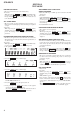
STR-DE375 SECTION 3 DIAGRAMS 3-1. CIRCUIT BOARDS LOCATION SECONDARY board VOL-SEL board (E model) STANDBY board PRIMARY board (except E model) POWER SWITCH board HEADPHONE board DISPLAY board MAIN board • WAVEFORMS – MAIN BOARD – 1 IC1 qf 2.2Vp-p 230ns – DISPLAY BOARD – 2 IC103 qa 5.
STR-DE375 THIS NOTE IS COMMON FOR PRINTED WIRING BOARDS AND SCHEMATIC DIAGRAMS. (In addition to this necessary note is printed in each block.) For schematic diagrams. Note: For printed wiring boards. Note: • All capacitors are in µF unless otherwise noted. pF: µµF 50 WV or less are not indicated except for electrolytics and tantalums. • All resistors are in Ω and 1/4 W or less unless otherwise specified. • % : indicates tolerance. • f : internal component. • 2 : nonflammable resistor.
STR-DE375 3-2.
STR-DE375 3-3. PRINTED WIRING BOARD – MAIN SECTION – IC 805 IC 1 IC 401 IC 807 R 408 C 416 C 417 IC 201 IC 202 TO TUNER UNIT C 467 IC 803 C 468 IC 802 IC 702 IC 801 IC 501 IC 701 IC 804 • Semiconductor Location Ref. No. D301 D470 D505 D506 D508 D510 D605 D606 D607 D608 D610 D627 D706 D710 D721 D722 D725 D726 Location D-1 C-8 F-4 F-4 F-3 C-10 F-8 F-8 F-7 F-8 C-9 F-11 F-6 C-11 E-11 D-11 G-10 F-10 Ref. No.
STR-DE375 3-4.
STR-DE375 3-5. SCHEMATIC DIAGRAM – MAIN SECTION(2/3) – 1.7uH 1.7uH 1.7uH 1.7uH 1.
STR-DE375 3-6.
STR-DE375 3-7. PRINTED WIRING BOARD – PANEL SECTION – CNS 204 DVD/MULTI CH TV/SAT IC 203 IC 103 (Page 10) PRESET/ PTY SELECT SOUND CONTROL FM/AM FM MODE PTY • Semiconductor Location Ref. No.
STR-DE375 3-8.
STR-DE375 IC 950 3-9.
STR-DE375 3-10.
STR-DE375 3-11. IC BLOCK DIAGRAMS 3-12. IC PIN FUNCTION DESCRIPTION IC103 µPD780206GF-092-3BA (DISPLAY BOARD) (NC) XO XI VDD2 VSS2 T1 T2 BU1924 (MAIN BAORD) RCLK IC1 16 15 14 13 12 11 10 9 CLOCK Pin No. Pin Name I/O 1 VDD +5V I Power supply to µ-com 2 S1 O Control Video IC switching (Not used) 3 S2 O Control Video IC switching (Not used) 4 IC.MUTE O Control mute of Video IC (Not used) 5 P34 — Not used 6 P33 — Not used 7 S.
STR-DE375 Pin No. Pin Name I/O 51 REAR-RY O Control rear relay on/off Description 52 CTR-RY O Control center relay 53 FRONT-RY O Control speaker relay 54 H/P-RY O Control Headphone relay 55 WOOFER RY O Control Woofer relay 56 SYS.POWER I Detect power switch key 57 P115 — Not used 58 P114 — Not used 59 FUNC.
STR-DE375 SECTION 4 EXPLODED VIEWS NOTE: • -XX, -X mean standardized parts, so they may have some differences from the original one. • Items marked “*” are not stocked since they are seldom required for routine service. Some delay should be anticipated when ordering these items. • The mechanical parts with no reference number in the exploded views are not supplied. • Hardware (# mark) list and accessories and packing materials are given in the last of this parts list.
STR-DE375 4-2. CHASSIS SECTION #2 #1 not supplied not supplied not supplied (PRIMARY board) #2 #1 66 59 60 58 #3 not supplied #3 T901 #1 65 #2 64 #2 57 52 #2 #1 55 not supplied 56 63 #2 62 not supplied 63 #2 61 #1 not supplied 62 51 Part No. Description 51 52 52 52 53 4-232-237-01 A-4475-758-A A-4475-857-A A-4476-441-A A-4475-757-A FOOT (DIA.
STR-DE375 SECTION 5 ELECTRICAL PARTS LIST DISPLAY NOTE: • Due to standardization, replacements in the parts list may be different from the parts specified in the diagrams or the components used on the set. • -XX, -X mean standardized parts, so they may have some difference from the original one. • Items marked “*” are not stocked since they are seldom required for routine service. Some delay should be anticipated when ordering these items. • CAPACITORS: uF: µF Ref. No. Part No.
STR-DE375 DISPLAY Ref. No. Part No. Description Remarks Ref. No. Part No.
STR-DE375 DISPLAY Ref. No. HEADPHONE MAIN Part No. Description Part No. Description S219 S220 S221 S222 S223 1-762-875-21 1-762-875-21 1-762-875-21 1-762-875-21 1-762-875-21 SWITCH, TACTILE (SF ON/OFF) SWITCH, TACTILE (SUR) SWITCH, TACTILE (MENU >) SWITCH, TACTILE (MENU +) SWITCH, TACTILE (ENTER) Remarks C303 C304 C305 C306 C307 1-126-794-11 1-124-465-00 1-126-794-11 1-136-167-00 1-126-962-11 ELECT ELECT ELECT FILM ELECT 4.7uF 0.47uF 4.7uF 0.15uF 3.3uF 20.00% 50V 20% 50V 20.00% 50V 5.
STR-DE375 MAIN Ref. No. Part No. Description C364 C365 C366 C367 C368 1-126-961-11 1-126-961-11 1-126-961-11 1-136-165-00 1-164-159-11 ELECT ELECT ELECT FILM CERAMIC 2.2uF 2.2uF 2.2uF 0.1uF 0.1uF Part No. Description 50V 50V 50V 50V 50V Remarks C520 C524 C526 C601 C603 1-128-813-11 1-126-795-11 1-127-876-31 1-126-794-11 1-104-665-11 CERAMIC ELECT CERAMIC ELECT ELECT 220PF 10uF 0.01uF 4.7uF 100uF 5% 50V 20.00% 50V 10% 50V 20.00% 50V 20.
STR-DE375 MAIN Ref. No. Part No. Description C804 C805 C806 C807 C808 1-165-498-11 1-130-781-00 1-130-781-00 1-104-664-11 1-104-664-11 ELECT MYLAR MYLAR ELECT ELECT Part No. Description 4700uF 0.22uF 0.22uF 47uF 47uF 20% 63V 5.00% 100V 5.00% 100V 20.00% 25V 20.00% 25V C808 Remarks D610 D627 D706 D710 D721 8-719-991-33 8-719-991-33 8-719-991-33 8-719-991-33 8-719-991-33 DIODE DIODE DIODE DIODE DIODE 1SS133T-77 1SS133T-77 1SS133T-77 1SS133T-77 1SS133T-77 1-124-465-00 ELECT 0.
STR-DE375 MAIN Ref. No. L651 L701 L751 Part No. Description Remarks Part No. Description < TRANSISTOR > Q752 Q753 Q753 Q754 Q754 8-729-141-30 8-749-010-25 8-729-020-52 8-749-010-26 8-729-020-48 TRANSISTOR 2SC3623ATP-LK IC MN2488-OPY-M (CND,SP,MY) TRANSISTOR 2SD2439-OPY (AEP,UK,E,AR) IC MP1620-OPY-M (CND,SP,MY) TRANSISTOR 2SB1588-OPY (AEP,UK,E,AR) TRANSISTOR TRANSISTOR TRANSISTOR TRANSISTOR TRANSISTOR 1-420-872-00 COIL, AIR-CORE 1.7uH 1-420-872-00 COIL, AIR-CORE 1.7uH 1-420-872-00 COIL, AIR-CORE 1.
STR-DE375 MAIN Ref. No. Part No. Description Remarks Ref. No. Part No. Description R443 R447 R448 R449 R450 1-249-418-11 1-249-436-11 1-249-436-11 1-249-433-11 1-249-437-11 CARBON CARBON CARBON CARBON CARBON 1.2K 39K 39K 22K 47K 5% 5% 5% 5% 5% 1/4W F 1/4W 1/4W 1/4W 1/4W R541 R573 R601 R602 R603 1-249-431-11 1-249-437-11 1-249-417-11 1-249-439-11 1-249-418-11 CARBON CARBON CARBON CARBON CARBON 15K 47K 1K 68K 1.
STR-DE375 MAIN Ref. No. Part No. Description R701 R702 R703 1-249-417-11 CARBON 1-249-439-11 CARBON 1-249-418-11 CARBON 1K 68K 1.2K R703 1-249-419-11 CARBON 1.5K R703 1-249-421-11 CARBON 2.2K R704 R705 R706 1-249-439-11 CARBON 1-249-433-11 CARBON 1-215-888-00 METAL OXIDE 68K 22K 220 R706 1-216-453-00 METAL OXIDE 270 R707 1-215-889-00 METAL OXIDE 330 R707 1-216-452-11 METAL OXIDE 180 R707 1-215-880-00 METAL OXIDE 10 R710 R711 1-249-421-11 CARBON 1-249-440-11 CARBON 2.
STR-DE375 MAIN Ref. No. POWER SWITCH Part No. SECONDARY Description Remarks STAND BY Ref. No. Part No. < VIBRATOR > Description Remarks < CONNECTOR > X1 1-579-900-11 VIBRATOR, CRYSTAL 4.33MHz (AEP,UK) ************************************************************ CNP901 1-564-321-00 PIN, CONNECTOR 2P < DIODE > 1-680-497-11 POWER SWITCH BOARD ******************** < CONNECTOR > * CNS104 1-564-518-11 PLUG, CONNECTOR 3P < RESISTOR > R239 1-249-425-11 CARBON 4.
STR-DE375 STAND BY Ref. No. Part No. Description Remarks Ref. No. Part No.
STR-DE375 REVISION HISTORY Clicking the version allows you to jump to the revised page. Also, clicking the version at the upper right on the revised page allows you to jump to the next revised page. Ver. Date 1.0 2001.