3-206-359-12(1) Digital Camcorder Operating Instructions Before operating the unit, please read this manual thoroughly and retain it for future reference. Note The supplied CD-ROM includes operation manuals for the DSR-370/570WS series of digital camcorders (English, Japanese, French, German, Italian and Spanish versions). For more details, see page 14 “Using the CD-ROM Manual.
Owner’s Record The model and serial numbers are located on the top. Record these numbers in the spaces provided below. Refer to them whenever you call upon your Sony dealer regarding this product. Serial No. Model No. WARNING To prevent fire or shock hazard, do not expose the unit to rain or moisture. To avoid electrical shock, do not open the cabinet. Refer servicing to qualified personnel only. CAUTION Danger of explosion if battery is incorrectly replaced.
Table of Contents Chapter 1 Overview Product Configurations .................................................... 9 Features ........................................................................... 10 Features of the DSR-370/370P/570WS/570WSP Camera Section .......................................................................... 10 Features of the DSR-570WS/570WSP Camera Section ... 12 Features of VCR Section ................................................... 12 Other Features .......................
Table of Contents Chapter 2 Fitting and Connections (Continued) Connections .................................................................... 50 Connecting a Number of Camcorders ............................... 50 Connecting an External VCR ............................................ 51 Connecting an i.LINK Digital Cassette Recorder ............. 51 Connecting a Camera Control Unit ................................... 52 Power Supply ...................................................................
Chapter 4 Viewfinder Screen Indications and Menus Viewfinder Screen Indications ....................................... 85 Changing the Viewfinder Display ..................................... 85 Viewfinder Normal Indications ....................................... 87 Status Indications .............................................................. 90 Viewfinder Basic Menu ................................................... 92 Basic Menu Operations .....................................................
Table of Contents Chapter 5 Adjustments and Settings (Continued) Menu 213 Selecting Audio Reference Level .................. 124 Menu 214 Setting Fade-In/Fade-Out for the Audio Recording Start and Stop Points ................................ 124 Menu 220 Using Setup Add (for DSR-370/570WS only) ....................................... 125 Menu 221 Using Setup Remove (for DSR-370/570WS only) ....................................... 125 White Balance Adjustment ...........................................
Appendix (Continued) Chart of Optional Components and Accessories ...... 151 What Is ClipLink? .......................................................... 152 How ClipLink Changes Video Production Techniques ... 152 ClipLink Operation Flow ............................................... 153 Example System Configuration ...................................... 153 Data Generated When Shooting ...................................... 154 Glossary ...................................................................
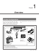
Chapter 1 Overview Product Configurations The eight models, DSR-370L/370PL, DSR-370K1/ 370PK1/, DSR-370K2/370PK2/ and DSR-570WSL/ 570WSPL, comprise both NTSC and PAL versions and the components as shown in the figure below. The operation of the basic camcorder is the same in all cases.
Features Chapter 1 Overview The DSR-370/370P is a 4:3 standard screen type digital camcorder. The DSR-570WS/570WSP is a 16:9 wide screen type (4:3/16:9 switchable) digital camcorder. The performance of the Camcorder CCDs is as follows. DSR-370/370P 1 /2-inch IT type Power HAD CCD The DSR-370/370P uses 1/2-inch IT type Power HAD CCDs which excel in reduction of smear, sensitivity and picture quality. • Smear: –110 dB • Sensitivity: F11.
Total level control system (TLCS) Even if the incoming light exceeds the range in which the standard auto iris can control exposure, the auto gain control (AGC) or auto exposure (AE) backs up to ensure proper exposure. Recording time (REC TIME) display Recording time can be displayed in either of the following modes.
Features Features of the DSR-570WS/ 570WSP Camera Section Chapter 1 Overview Following are features of the DSR-570WS/570WSP, considered only as a 16:9 wide screen type camcorder. For features which are common with the DSR-370/ 370P 4:3 standard screen type camcorder, see “Features of the DSR-370/370P/570WS/570WSP Camera Section” on the previous page.
Equipped with DV OUT connector Recording/playback can be set to audio lock mode. You are able to select between two-channel recording (with a sampling frequency of 48 kHz) mode or fourchannel recording (with a sampling frequency of 32 kHz) mode (CH-1 and CH-2 only). The DV OUT connector is i.LINK1) compatible. You can connect Sony equipment with DV input connectors.
Location Function of Parts Usingand the CD-ROM Manual The supplied CD-ROM includes operation manuals for the DSR-370/570WS series of digital camcorders and players (English, Japanese, French, German, Italian and Spanish versions). Chapter 1 Overview CD-ROM System Requirements The following are required to access the supplied CDROM disc. • Computer: PC with MMX Pentium 166 MHz or faster CPU, or Macintosh computer with PowerPC CPU.
Location and Function of Parts Front View 1 MIC IN +48 V connector 2 VF connector 3 FILTER control 4 Lens mount 5 SHUTTER switch 6 TAKE button 7 AUDIO LEVEL knob 8 WHT/BLK switch 9 VTR button 1 MIC (microphone) IN +48 V connector (XLR 3pin, female) Connect the supplied microphone or an optional microphone (operable with a 48 V supply). 6 TAKE button Press this button to specify an editing point (Mark IN/ OUT or Cue point) at the current tape position during shooting. (See page 79.
Location and Function of Parts Right Side View Front section Chapter 1 Overview 1 EZ FOCUS button 2 EDIT SEARCH buttons 3 LIGHT switch 4 EZ MODE button and indicator 5 ZEBRA button and indicator 6 A.IRIS MODE switch and indicator 7 MENU switch 8 W.BAL switch 9 MENU dial 0 POWER switch qa OUTPUT/DL/DCC+ switch qs NG button qd GAIN switch qf ATW button and indicator 1 EZ FOCUS button Press this button to turn the “easy focus” function on. This opens the iris, to make it easier to focus before shooting.
Note EZ mode does not function in the following cases. • When the RM-M7G Remote Control Unit is connected • When the CCU-M5A/M5AP Camera Control Unit is connected • When external analog signals are being input. 5 ZEBRA button and indicator Depress this button to display a zebra pattern (diagonal stripes) in the viewfinder.
Location and Function of Parts Rear section 1 EJECT button Chapter 1 Overview EJECT STOP REW PLAY F FWD 2 Tape transport buttons and indicators 3 EARPHONE connector 4 WARNING indicator 5 LIGHT switch 6 DISPLAY switch 7 AUDIO LEVEL (CH-1/CH-2) knobs 8 Display window 9 RESET/(MENU SET) button 0 Speaker qa ALARM knob qs MONITOR knob 1 EJECT Z button Press to open the cassette holder (1 on page 27) when the camcorder is powered.
The audio levels are indicated in the display window 8. For details, see “8 Display window”. 7 AUDIO LEVEL (CH-1/CH-2) (audio recording level adjustments for channels 1 and 2) knobs When the AUDIO SELECT (CH-1/CH-2) switches (4 on page 23) are set to MAN, these knobs adjust the audio levels being recorded on channels 1 and 2.
Location and Function of Parts Indications in the display window (continued) Indication Description J Lithium backup Appears when the voltage of the internal lithium backup battery (CR2032) is low. If this battery warning indication appears, replace the lithium backup battery immediately. Chapter 1 Overview For further information about replacing lithium battery, see “Inserting and Replacing the Lithium Battery” (page 37).
Indications in the display window (continued) Indication Description Q Tape remaining indication During recording or pause mode, this indication shows the remaining tape time as shown below. It is not displayed when no cassette is loaded.
Location and Function of Parts qa ALARM (alarm tone volume adjustment) knob Controls the volume of the warning tone that is output via the speaker (0 on page 21) or EARPHONE connector (3 on page 18). Turning this knob to the minimum setting mutes the alarm tone. Chapter 1 Overview qs MONITOR (monitor volume adjustment) knob Controls the volume of the sound other than the warning tone that is output via the speaker (0 on page 21) or EARPHONE connector (3 on page 18).
For time code and user bit settings, see page 71. On how to use the SHIFT button for menu settings, see “Setting on the VCR Section —VCR Menu” (page 117). 4 AUDIO SELECT (CH-1/CH-2) (audio recording level adjustments manual/auto selection for channels 1 and 2) switches These select the audio recording level adjustment method. AUTO: Use the AGC (automatic gain control) circuit to automatically adjust the audio level.
Location and Function of Parts 0 ClipLink CONTINUE button When restarting ClipLink shooting, press this button to add the new clip at the end of the recorded clips. Note Chapter 1 Overview When restart recording without pressing this button, the pre-recorded ClipLink log data and Index Pictures are deleted. For details , see “ClipLink Shooting” (page 77). qa MONITOR SELECT (audio monitor selection) switch Selects audio output via the speaker (0 on page 21) or earphone.
Note 2 SKIN DTL (skin detail) switch Set this switch to ON to use the skin detail correction function. For details, see “Skin Detail Correction” (page 138). 3 EXT VTR OUTPUT switch Depending on the external VCR connected to the VTR/CCU connector (0 on page 29), this switches the video signal output to the VCR.
Location and Function of Parts Left and Upper View Front section Chapter 1 Overview 1 Shoulder strap fitting 2 Attachment shoe for large viewfinder 3 Accessory fitting shoe and screw hole 4 Viewfinder left-to-right positioning ring 5 Viewfinder fitting shoe 6 REMOTE connector 1 7 Viewfinder front-to-back position locking knob 8 Fitting for optional microphone holder 9 Video light connector 0 LENS connector qa VIDEO OUT connector qs REMOTE connector 2 1 Shoulder strap fitting To use the supplied shoulder
8 Fitting for optional microphone holder You can fit an optional CAC-12 Microphone Holder here. (See page 43.) 0 LENS connector (12-pin) If you use a lens with cable, connect the lens cable. qa VIDEO OUT connector (BNC) This outputs the video signal captured by the camcorder. Notes • EZ mode cannot be used if the RM-M7G is connected to the camcorder. • Be sure to turn off the power of the camcorder before connecting the RM-M7G.
Location and Function of Parts 3 TC IN (time code input) connector (BNC) Input an external signal for synchronizing the built-in time code generator. Use an SMPTE (DSR-370/ 570WS) or EBU (DSR-370P/570WSP) time code signal. Chapter 1 Overview Note Use a jitterless LTC signal. Using an LTC signal reproduced by other equipment may cause the camcorder to malfunction. 4 TC OUT (time code output) connector (BNC) This outputs time code signals from the built-in time code generator.
See “Connecting to Audio System” (page 46) for more information about how to connect a UHF synthesizer tuner. See “Connecting a CA-370 Intercom Adaptor” (page 48) for more information about how to connect an intercom adaptor. 2 TALLY switch Set this switch to ON to activate the TALLY indicator 1 function. 7 Cable clamp Fasten an i.LINK cable (DV connecting cable) to the clamp using the supplied binding tie so that the plug is not pulled out from the DV OUT connector 8.
Location and Function of Parts Chapter 1 Overview • When this connector is used with a battery pack attached, operation may be interrupted due to exhaustion of the batteries. To prevent this, see “Avoiding breaks in operation due to dead batteries” (page 54). • When a CCU is connected to this connector and a battery pack is attached, power is supplied automatically from the battery pack. Always power off the camcorder before attaching or detaching a battery pack or switching the power.
1 Iris ring For manual iris control, set the Iris selector qs to the “M” position, and turn this ring. 3 Focus ring Turn this ring to focus the lens on the subject. 4 MACRO (close-up) selector For close-up work, turn the MACRO ring 6 while holding this button down. (See page 135.) 5 F.f (flange focal length) adjustment ring and F.f (flange focal length) fixing knob F.f adjustment ring : To adjust the flange focal length, loosen the F.f fixing knob, then turn the ring. (See page 133.) F.
Location and Function of Parts VCL-719BX Zoom Lens (for DSR-370K1/370PK1) When using a lens other than VCL-716BX or VCL-719BX, see page 40 and page 134 (“Designating the lens”). Chapter 1 Overview 1 Iris ring 2 Zoom ring 4 M (close-up) button 5 F.B adjustment ring and F.
6 MACRO (close-up) ring For close-up, turn this ring while holding the M button down. (See page 135.) 7 ZOOM selector This selects the mode of zoom operation. SERVO: power zoom MANU. (manual): manual zoom 8 Zoom remote control connector (8-pin) Connect the optional Lens Remote Control Unit for remote control of zooming. 9 VTR button This button starts and stops recording on the VCR. Press it once to start recording, and once more to stop. 0 Shtl button Use this for shuttle shot function (see next page).
Location and Function of Parts Shuttle shot function Chapter 1 Overview What is the shuttle shot function? The shuttle shot function allows you to zoom at maximum speed to a preset position (shuttle memory position) simply by pressing the lens Shtl button. When you release the Shtl button, the lens returns to the original position. Position before operation Shtl button Shuttle memory position Hold Shtl button down. Release Shtl button.
DXF-801/801CE Viewfinder Note camera or camcorder. It operates in 4:3 mode when connected to the DSR-370/370P. It operates in either 4:3 or 16:9 mode when connected to the DSR-570WS/ 570WSP.
Location and Function of Parts Chapter 1 Overview 6 REC/TALLY (recording/tally) indicators (red) • These flashe from the time when you press the VTR button on the lens or camcorder until recording starts, then stay on continuously during recording. • These are also used to indicate a fault. (See page 142.) • When a CCU (camera control unit) is connected, these indicators light only when a CALL signal is received from the CCU. They do not light or flash during VCR recording or in the case of a VCR fault.
Chapter 2 Fitting and Connections Inserting and Replacing the Lithium Battery This camcorder uses a lithium battery to retain stored data. When using the camcorder for the first time, be sure to insert the supplied lithium battery (CR2032). The camcorder will not operate correctly without this lithium battery. Lifetime of the lithium battery When the lithium battery’s voltage falls, the lithium backup battery warning Li appears in the display window.
Inserting and Replacing the Lithium Battery 1 Turn the POWER switch on. 2 Press down the catch at the top of the battery cover and open the cover. 2 Catch Press and pull forward. LI LITHIUM BATT Battery cover Chapter 2 Fitting and Connections 1 POWER switch 3 Take out the lithium battery. Press down and pull out toward you. 4 Reverse step 3 to insert a replacement lithium battery. Make sure that the + symbol on the battery is facing you. 5 Close the battery cover.
Fitting the Lens Use the following procedure to fit the lens. Note Be sure to turn off the power before fitting the lens. 1 Remove the retaining rubber which prevents the lens mount from coming loose, then raise the lens fixing lever, and remove the lens mount cap. Retaining rubber 2 Chapter 2 Fitting and Connections Lens mount cap Lens fixing lever With the lens fixing lever turned fully counterclockwise, push in the lens, aligning the projection on the lens with the cutout on the camcorder.
Fitting the Lens Chapter 2 Fitting and Connections If using a 1/2” lens other than the VCL-716BX/ 719BX on DSR-370/370P If the connector on the lens attachment section is a 14pin connector (VCL-714BXA and other lenses), then the lens may be operated in the same way as the VCL716BX/719BX. If the lens has a 7-pin connector, then the following limitations apply. • The lens iris f. value is not displayed in the viewfinder. • Iris operation may be slow in auto iris mode, and hunting may occur.
Using Accessories Using the Viewfinder Removing the Viewfinder Remove any microphone from the viewfinder before beginning. Pull the viewfinder connector out of the VF connector on the front. 2 Loosen the viewfinder left-toright position fixing ring, then pulling up the retaining catch, slide the viewfinder out. To fit the viewfinder Reverse the removal procedure. (You need not hold the viewfinder stopper up.
Using Accessories Fitting the 5-inch Electronic Viewfinder You can fit the optional DXF-51/51CE (5-inch)/(DXF41/41CE (4-inch)) Electronic Viewfinder. To fit, the following parts are required. How to fit Remove the cover of the grip and attach the shoe and stopper screw (accessory shoe kit). VF Cable Required parts to fit Name Part No.
Using an Optional Microphone Fitting the optional CAC-12 Microphone Holder Remove the two retaining screws (M3 × 8) for the optional microphone holder, then use these screws to attach the CAC-12 Microphone Holder. Screws removed from the camcorder Chapter 2 Fitting and Connections CAC-12 Fitting an optional microphone Use the following procedure to attach an optional ECM-670 Microphone.
Using Accessories Fitting optional microphones (operable with a 48 V supply) other than the ECM-670 Use the same fitting procedure as for the ECM-670, but note the following differences with respect to the microphone adaptor. ECM-672: no microphone adaptor required. Slender microphones (19 mm (3/4 inch) diameter): use the microphone adaptor supplied with the CAC-12. Using a Video Light Chapter 2 Fitting and Connections You can use the Anton Bauer Ultralight 2 or equivalent for this comcorder.
When using equipment other than this camcorder for power supply Break off projections A and B on the camcorder. (See step 1 of the previous section “When using a video light with a long cable”.) Insert the cable into the grip from the front hole and take out from the rear hole as shown in the figure. Chapter 2 Fitting and Connections Fitting the Shoulder Strap This section describes the procedure for fitting the supplied shoulder strap to the camcorder.
Using Accessories Removing the shoulder strap g Chapter 2 Fitting and Connections Press here to release. Connecting to Audio System The camcorder is able to record sound not only from the attached microphone but also from a wireless microphone or an external audio system. For connecting an intercom adaptor, see page 48.
3 Fit the attachment plate on the rear side of the CA-WR855 to the V-groove on the battery attachment interface, and then slide the CA-WR855 down until it connects to the WRR connector. CA-WR855 Chapter 2 Fitting and Connections 4 Set one of the AUDIO IN (CH1/CH-2) switches to WIRELESS. To connect a WRR-810A/860A Attach the WRR tuner fitting (not supplied) (Part No. A-8278-057-A) to the rear of the camcorder as shown in the following figure.
Using Accessories Using an external audio system Connect an audio mixer or other external audio system component to the AUDIO IN CH-1/CH-2 connector as shown below. AUDIO IN (CH-1/CH-2) switches: Set to REAR. CH-1 CH-2 AUDIO IN FRONT Chapter 2 Fitting and Connections VJ MIC WIRELESS REAR Input selection switch: Set to LINE. +48V ON LINE AUDIO IN CH-1/CH-2 MIC To audio mixer, etc.
Connecting the CA-370 Intercom Adaptor to this camcorder Fit the attachment plate on the read side of the CA-370 to the V-groove on the battery attachment interface, and then slide the CA-370 down until it connects to the WRR connector. Chapter 2 Fitting and Connections CA-370 WRR connector Using the Optional LC-DS500 Carrying Case For details on using the carrying case, refer to the instruction manual supplied with the carrying case.
Connections Connecting a Number of Camcorders When using two or more synchronized camcorders, connect an external sync signal to the GEN LOCK IN connector, supplying a VBS or BS signal. The camcorder will then operate synchronized to this signal. You can adjust the synchronization using the basic menu page 5. (See page 94.) Note When you fit the optional DSBK-501/501P, set the VIDEO IN to CAM using the basic menu page 4. (see page 93.
Connecting an External VCR You can connect the following external VCRs to the VTR/CCU connector (26-pin) or the DV OUT connector for recording. VCR Connecting cable VTR/CCU connector BVW-50/50P/35/ 35P (portable) CCZ-A Camera cable (max. length 10 m (33 ft.)) DV OUT connector Digital Videocassette Recorder DSR20/20P/70A/ 70AP/2000/ 2000P, etc. i.LINK cable (DV connecting cable) (max. length 4.5 m (14 ft.
Connections Connecting a Camera Control Unit You can connect CCU-M5A/M5AP Camera Control Unit (CCU) to the VTR/CCU connector of this camcorder. Chapter 2 Fitting and Connections Note the following when connecting a CCU. • The only video signal formats that can be transmitted from this camcorder to the CCU are VBS and R–Y/ B–Y/Y. • A CCU cannot be used at the same time as a remote control device connected to the REMOTE1 or REMOTE2 connector of this camcorder.
Power Supply The following power supplies can be used with this camcorder. • BP-L40/L40A/L60/L60A/L90/L90A lithium-ion battery pack • BP-M50/M100 nickel metal hydride battery pack • NP-1B Ni-Cd Battery Pack (The DC-L1Battery Adaptor is required.) • BP-90A Ni-Cd Battery Pack (The DC-L90 Battery Adaptor is required.) • AC power (The AC-550/550CE, AC-DN1, ACDN2B or CMA-8A/8ACE AC Adaptor is required.
Power Supply Attaching the battery pack 1 Chapter 2 Fitting and Connections 2 Press the battery pack against the rear of the camcorder, aligning the side line of the battery pack with the line on the camcorder. LOCK BP-L40/L40A/L60/L60A/L90/L90A/ M50/M100 Align these lines. Slide the battery pack down until its “LOCK” arrow points at the matching line on the camcorder. Matching line on the camcorder Detaching the battery pack Holding the button in, pull the battery pack up.
Using an AC Adaptor Using the Anton Bauer Intelligent Battery System Using a CMA-8A/8ACE AC Adaptor Connect the camcorder to the AC power supply as shown in the following figure, and turn the POWER switch of the CMA-8A/8ACE ON. To AC power source Contact your Sony dealer for more information. POWER switch: ON LOCK CCQX-3 cable CAMERA/CCU DC IN Using an AC-DN1 AC Adaptor Mount the AC-DN1 on the camcorder in the same way as a battery, then connect to the AC power source.
Chapter 3 Shooting Basic Procedure for Shooting RET button ZEBRA button Focusing ring POWER switch FILTER control VTR button 1 2 Power the camcorder. Set the FILTER control appropriately for the lighting conditions.
Basic Procedure for Shooting Filter setting Lighting conditions 11Setup the VCR section according to your shooting 1 (3200) Studio halogen lighting (incandescent), sunrise and sunset. objectives, then start recording. 2 (5600K + 1 /8 ND) Sunlight. Use it to prevent hunting1) or to reduce the depth of field2). 3 (5600K) Cloudy or rainy outdoor shooting, and fluorescent lighting. 4 (5600K + 1 /64ND) Sunlight. Use it to prevent hunting1) or to reduce the depth of field2).
Recording Notes on using cassettes Usable Cassettes DVCAM cassettes Preventing accidental erasure The following figure illustrates the DVCAM cassette’s appearance. Set the REC/SAVE switch to SAVE to prevent accidental erasure of recorded contents. Model name Size PDV-64*/94*/124*/184*/34* Standard size PDVM-12*/22*/32*/40* Mini size The * in each model name is actually “ME” (indicating that a cassette memory is contained), or “N” (indicating that no cassette memory is contained).
Recording Checking the tape for slack Turn the reel gently in the direction shown by the arrow. If the reel does not move, there is no slack. Insert the cassette into the cassette holder, close the cassette holder, and after about 10 seconds take it out. Paper clip, etc. See page 61 on how to insert a cassette. Reel Recording on the Internal VCR Chapter 3 Shooting This section describes basic recording operations using the internal VCR.
1 Set the POWER switch to ON and check the following items in the display window. Item to check Indication and steps See also How is the battery? BATT E [xxxxxx] F: The battery is fully charged. If two or fewer marks appear and the indication is blinking, replace the battery. “8 Display window” (page 19) Has the lithium battery been inserted and is it charged? Make sure that the Li is not shown in the display window. If it is shown, replace the lithium battery.
Recording operation buttons inoperable, press on the “PUSH” indication again to make sure that the cassette holder is solidly closed. Notes • Turn the power on and then insert or eject the cassette. • When inserting a mini-size cassette, confirm the cassette is under the lock (see the above figure), and then close the cassette holder. If the cassette is not inserted fully under the lock, a stopper will prevent the cassette holder from closing when you press down on it.
4 Display menu 212 and select the audio recording mode (two-channel mode or four-channel mode). During recording, the tape transport buttons (EJECT, REW, F FWD, PLAY, and STOP) cannot be used. For menu operation, see “Selecting Audio Recording Mode — Menu 212” (page 123). Note One of the following warning indications appears in the display area when you change the audio mode setting during recording pause. Operation Step To view image being shot • Look into the viewfinder.
Recording When the battery is getting exhausted When the battery is getting exhausted, the BATT indication in the display window blinks once a second (see page 20). Replace the battery with a charged battery immediately. If you continue to use the low battery, the BATT indication will blink four times a second, and the operation will stop. For description of how to replace batteries, see “Power Supply” on page 53. Note Turn the POWER switch OFF before replacing the battery.
To operate either VCR during recording, change the VTR TRIGGER switch setting. Both VCRs continue recording at the time of switching. Setting to INT ONLY: The camcorder can operate only the internal VCR. Setting to EXT ONLY: The camcorder can operate only the external VCR. Recording on the internal and external VCRs simultaneously 1 Set the switches as shown in the table below. Switch Setting VTR TRIGGER switch PARALLEL EXT VTR OUTPUT switch Set depending on the connected VCR.
Recording Using the viewfinder to see playback pictures To see playback pictures of the internal VCR Press the PLAY button. Chapter 3 Shooting To see playback pictures of an external VCR For an external VCR connected to the VTR/CCU connector: Press the RET button on the lens when the internal VCR is recording or no cassette is loaded in the internal VCR. While holding down the RET button, you can see the return video from the external VCR.
Back Space Editing This section describes the steps for recording several scenes continuously. 1 Follow steps 1 to 5 (pages 60 to 63) in the procedure “Recording on the Internal VCR” to begin recording. To continue the time code that has been recorded on the tape, set the TC mode switch 2 to R-RUN in step 3 (page 62). For details of time codes, see “Setting the Time Code Value” on page 73.
Back Space Editing • If the POWER switch is turned on and off repeatedly. • If the camcorder is left powered off for several hours. • If the camcorder is subject to severe vibration while powered off. • If for any other reason the automatic recording continuity function is unable to operate correctly. • If the lithium battery (CR2032) is exhausted, or if no lithium battery has been fitted.
To change the playback speed Press the REV or FWD button down firmly into the inner position to make the tape move at the faster speed. Press the button down lightly to make the tape move at the slower speed. The following indication appears on the screen. Note Do not shut off the power while using the edit search function. The VCR may not be able to find the continue point. 4 For details of the playback operation, see page 70.
Playback — Checking Recorded Contents Checking the Recorded Contents Immediately After Shooting — Recording Review Immediately after shooting, you can use the recording review function to automatically rewind and play back the last 2 to 10 seconds of the recording to check the recorded contents. STOP button REW button PLAY button Performing recording review With recording paused, press the RET button on the lens.
Setting Time Values The camcorder uses three types of time values: counter values, time code values, and user bits. The time value is displayed in the viewfinder screen and in the display window. PB DATE NDF EXT-LK H MIN HOLD SEC OVER dB OVER The counter value starts advancing as the tape is transported. It shows negative values if the tape is rewound past the point where the counter was reset.
Setting Time Values Setting the User Bit Value You can set the user bits as eight-digit hexadecimal values (base 16) to have the date, time, scene number, and other information inserted into the time code. When using both the time code and user bits, set up the user bits first. If you set the time code first, the internal time code generator will remain stopped while you set the user bits, which will set the time value off from the original setting.
Setting the Time Code Value For details of setting user bits, see “Setting the User Bit Value” on previous page. This section describes the steps for setting time code recording methods for particular shooting conditions and setting initial values. When using both the time code and user bits, setup the user bits first. If you set the time code first, the internal time code generator will remain stopped while you set the user bits, which will set the time value off from the original setting.
Setting Time Values 6 Operation Setting Time code advances freely regardless of the VCR’s current operation mode. F-RUN Restarting an interrupted recording Perform the following steps to make the time code continuous when the recording has been interrupted or when the cassette tape has been removed from the camcorder between shootings. Time code value advances only while recording. R-RUN 1 Use the TC mode switch 2 to set the desired running mode.
Synchronization With External Time Code Signals — Gen-Lock To edit and compile a recording that is shot using multiple camcorders, it is necessary to synchronize the video and time code of the various camcorders (by gen-lock). Note Synchronization with external time code signals (by gen-lock) may be disallowed in some cases at ClipLink shooting.
Setting Time Values Locking the internal time code generator to the reference time code Perform the following steps to synchronize the camcorder’s internal time code generator to an external time code. 1 2 3 Set the TC mode switch 1 to PRESET. Set the TC mode switch 2 to F-RUN. Connect a reference time code and video signal to the camcorder. For connections, see the previous section “Connection for gen-lock”. Chapter 3 Shooting “EXT-LK” will be displayed in the display window.
ClipLink Shooting The ClipLink function is intended to be used at various stages from recording to editing. When you record using this function, Index Pictures are automatically recorded along with the time code, scene number, and other data, all of which make for more efficient editing. Notes • When external equipment, such as a VCR, is connected to the DV OUT connector, you cannot shoot with ClipLink. • On this camcorder, you can also use the ClipLink function without recording Index Pictures.
ClipLink Shooting CLIP and IP from that data on ClipLink mode. • The number of recordable clips varies with cassette memory capacity. Up to 45 clips (Index Pictures) can be recorded in a 4-Kbit cassette memory and up to 198 clips (Index Pictures) can be recorded in a 16-Kbit cassette memory. appear in the display window. Display Meaning CLIP The camcorder is in ClipLink mode. IP The camcorder is in ClipLink mode and can record Index Pictures (when the DSBK-301A is fitted).
To continuously record the next scene Repeat steps 4 and 5. The scene number will be automatically incremented from the previous number. You can set or clear an “NG” designation for the previously recorded scene before shooting the next scene. If you have stopped the recording, see “Resuming Recording in ClipLink Mode” (page 81). Notes For details, see “Resuming Recording in ClipLink Mode” (page 81). You can use the TAKE button to record a time code for a Cue point or a Mark IN/OUT point.
ClipLink Shooting 4 Press the TAKE button when you find a shot where you would like to set a Mark IN point. Setting Cue points as you shoot The following data is recorded onto the cassette when you specify a Cue point to highlight a scene. TAKE button The TAKE/TALLY indicator (orange) lights in the viewfinder and “TAKE” appears on the screen. 5 Chapter 3 Shooting Press the TAKE button when you find a shot where you would like to set a Mark OUT point.
6 Time codes (HH:MM:SS) and scene number (scene 001) are recorded to the cassette memory and the Index Picture of the Rec IN point is recorded onto the tape (when the DSBK-301A is attached). To finish shooting, press the VTR button on the camcorder or lens. This stops recording operation. Resuming Recording in ClipLink Mode You can avoid this and continue recording in ClipLink mode from the previous recording stop point by performing the following steps.
ClipLink Shooting 4 Press the ClipLink CONTINUE button. The tape remaining indication in the display window flashes as the camcorder automatically searches the recording stop point. When it finds the recording stop point, it stops and enters recording pause mode. Once it has stopped, check that the CONT indication appears in the display window.
When recording in ClipLink mode is started and previous recording is overwritten Previous recording New recording Previous Index Pictures: erased New Index Pictures are recorded (when the DSBK-301A is fitted). ClipLink log data: overwritten by new data When recording in ClipLink mode is started after a previous recording New recording Previous Index Pictures: retained but invalid Chapter 3 Shooting Previous recording New Index Pictures are recorded (when the DSBK-301A is fitted).
Chapter 4 Viewfinder Screen Indications and Menus Viewfinder Screen Indications Changing the Viewfinder Display POWER switch MENU switch Chapter 4 STATUS MENU dial ON OFF MENU Use the dial and switches shown in the following figure to switch the viewfinder display among the normal indications, basic menu pages and advanced menu pages.
Viewfinder Screen Indications Displaying the normal indications and switching to the basic menu To display the normal indications, move the POWER switch to the ON position. To switch to and from the basic menu, use the MENU switch or MENU dial. “CHECK DIAG” appears before basic menu page 1 when the self diagnostic function has detected an abnormality. (see page 97.) Display by holding the MENU switch up while the normal indications are present.
Viewfinder Normal Indications During normal operation, the following items can be indicated in the viewfinder.
Viewfinder Normal Indications 0 Audio recording level indicators These show the recording levels of audio channels 1 and 2.
Indication Meaning Indication Meaning AUDIO 48kHz? At back space editing, you are switching from 32 kHz audio recording mode (4-channel mode) to 48 kHz audio recording mode (2-channel mode). PARA Simultaneous recording of the internal and external VCRs INT Recording on the internal VCR EXT Recording on the external VCR AUDIO 32kHz? At back space editing, you are switching from 48 kHz audio recording mode (2-channel mode) to 32 kHz audio recording mode (4-channel mode).
Viewfinder Normal Indications If an error message appears, contact your Sony dealer. Example indication Meaning 18 dB Gain setting is 18 dB. DPR 18 dB The DPR function is enabled. In this case the DPR function approximately doubles the gain (an increase of 6 dB) over the current gain setting (in this case 18 dB). HYPER The HYPER GAIN switch is in the ON position.
Notes • Status indicators will not be displayed during EZ mode. • When the CCU function switch is set to TITLE ON, the title display is given priority and the normal status display (see page 86) does not appear. However, the status display does appear while you press the camcorder’s MENU switch up to the STATUS side and hold it there.
Viewfinder Basic Menu To display the basic menu pages, press the MENU switch downward (to ON position) or press the MENU dial while the normal indications are being shown in the viewfinder. The basic menu configuration can include up to nine pages. (The configuration depends on the switch settings.) Contents and Settings of Each Menu Page Each page’s contents and settings are described below. Basic menu page 1 Basic Menu Operations The common operations on all basic menu pages are described below.
Basic menu page 2 Basic menu page 4 This is displayed when the optional DSBK-501/501P Analog Composite Input Board is fitted to the camcorder. Item Settings SKIN DTL Sets the amount of skin detail correction. 0.0 to 0.5 (normal value) to 1.0 Smaller values set a softer skin detail. DL LEV Sets the DynaLatitude level. LOW, STD (normal value), HIGH Set the amount of DynaLatitude effects as high level, standard level (STD), or low level.
Viewfinder Basic Menu Basic menu page 5 Item Settings This menu is displayed when CAM is selected on the basic menu page 4 and an external sync signal is input to the GEN LOCK IN connector. MARKER Sets marker display ON/OFF. ON (normal value), OFF Markers are displayed when this setting is ON and is not displayed when it is OFF. When the setting is ON, go to advanced menu page 4 to select the type of marker (see page 102). DUR TIME Sets the recording time.
3 Basic menu page 7 Turn the MENU dial until the desired character appears, and press it. The character cycles through the following sequence. Item CHG REEL NO. Sets the cassette name/number 4 5 Turn the MENU dial to move the text entry arrow. 6 After completing text entry, move the text entry cursor to the parenthesis position. Settings MARK/CUE MARK (normal value), CUE Selects Mark mode See “ClipLink Shooting” (page 77). or Cue mode (Space) See “To set the cassette name/ number” below.
Viewfinder Basic Menu 3 Basic menu pages 8 and 9 Press the MENU dial. This brings up the cursor on the screen, and switches to cursor transport mode. You can create a title of up to four lines, each of twelve alphanumeric or punctuation characters, and then save it. It is then possible to record the title over the picture while shooting. Initial cursor position Note You cannot set the skin detail correction while a title is displayed.
To record a title (basic menu page 9) 1 Access basic menu page 9 (title display). 2 Press the MENU dial once. When “CHECK DIAG” is displayed The “CHECK DIAG” indication appears in the status display area whenever the camcorder’s automatic self diagnostic function detects an abnormality. Access this page and perform error checking. (This page is displayed as basic menu page 1.) “CHECK DIAG” will also be displayed if there is a problem on the sync signal input to the GEN LOCK IN connector.
Viewfinder Advanced Menu Advanced Menu Operations To reinitialize all settings in the advanced menu to their factory defaults See also the figure on next page. To display the advanced menu Move the POWER switch to the ON position while holding down the MENU dial. Note The advanced menu does not appear when the camcorder is in EZ mode. Take the camcorder out of EZ mode first. To change the page Align the cursor to the page number and press the MENU dial so that the page number is blinking.
The following example shows settings for the DSR570WS/570WSP. The settings are somewhat different from those for the DSR-370/370P. Normal indications Move the POWER switch to the ON position with the MENU dial held down. Turn the MENU dial.a) Advanced menu page 2 Advanced menu page 1 Press the MENU dial.b) Confirmation screen Align the cursor to “ALL RESET” and press the MENU dial. Turn the MENU dial.a) Turn the MENU dial (to cancel resetting). Advanced menu page 3 Press the MENU dial.
Viewfinder Advanced Menu Contents and Settings of Each Menu Page Each page’s contents and settings are described below. Advanced menu page 2 Advanced menu page 1 The following example is for the DSR-570WS/ 570WSP. HYPER is not displayed for the DSR-370/ 370P. Use this page to return all menu settings to their factory preset values. For details of this operation, see “Advanced Menu Operations” (page 98). Item Settings GAIN This sets gain values for the positions of the GAIN switch.
Advanced menu page 3 Item Settings AWB MEM Selects whether or not to make the FILTER control settings (1 to 4) correspond to separate white balance adjustment values stored in memory. a) For DSR-370P/570WSP: EBU75 BAUD RATE Sets a baud rate for a computer connected to the REMOTE connector 2 (to be supported in the future version). iLINK CTL Selects whether to control from the camera the start and stop of recording by the external VCR connected to the DV OUT connector.
Viewfinder Advanced Menu Advanced menu page 4 Item ZEBRA Selects type of zebra pattern display. 1 (normal value): Displays the zebra pattern over parts having a video level. between 70 and 90 IRE (or 70 and 90%). Use the next item (ZEBRA1) to select the base level. 2: Displays the zebra pattern over parts having video levels of 100 IRE or above (or 100% or above). 1/2: Dual display (both 1 and 2) ZEBRA1 Sets base level for zebra pattern 1.
Advanced menu page 5 Item Settings SS INDa) Selects the mode for showing the shutter setting when displaying the normal indications. 3SEC: Displays shutter setting for three seconds only when the setting has been changed. ALWAYS (normal value): Displays the shutter setting at all times. ON (normal value): LL INDa) Selects whether or not to Displays. show the LOW LIGHT OFF: Not display. indication on the normal indications when inadequate lighting is detected.
Viewfinder Advanced Menu 2 Press and turn the MENU dial to move the text entry arrow. Turn the MENU dial downward to move the cursor to the right, or upward to move it to the left. 3 Press and turn the MENU dial to enter the desired characters. The displayed character changes as you turn the dial. 4 Return to step 2 and repeat the text entry procedure. 5 When you have finished entering the text, press and turn the MENU dial to move the cursor to the parenthesis position.
Advanced menu page 8 Item Settings CLOCK IND Selects whether or not to display the date/time on the normal indications. OFF (normal value): Not display. CAM: Displays. BARS: Displays only when color bars are displayed. DATE MODE Selects the date display format. YY MM DD (normal value): Year/month/day MM DD YY : Month/day/ year DD MM YY : Day/month/ year Item Settings 16:9/4:3 Selects whether to put the camera in 16:9 mode or 4:3 mode.
Viewfinder Advanced Menu Advanced menu pages 9 to 12 (DSR-370/ 370P) or pages 10 to 13 (DSR-570WS/ 570WSP) These pages are displayed only when the SETUP switch has been to FILE. For details of this operation, see “Setup Files” (page 108). Advanced menu pages 13, 14 (DSR-370/ 370P) or pages 14, 15 (DSR-570WS/ 570WSP) These pages are displayed only when the SETUP switch has been to FILE. For details of this operation, see “Using SetupNavi and SetupLog” (page 113).
Video Output and Viewfinder Picture (DSR-570WS/570WSP only) The video output and viewfinder picture of DSR570WS/570WSP vary as shown below according to the settings of the 16:9/4:3 item and the VF SCAN item of the advanced menu page 9. Subject 2 /3-inch optics Item Settings 16:9/4:3 16:9 VF SCAN AUTO The camera outputs 16:9 video. The scan size of the viewfinder picture is 16:9 size. Viewfinder picture Settings 16:9/4:3 16:9 VF SCAN FULL The camera outputs 16:9 video.
Setup Files You can use setup files to reproduce a particular configuration of settings. You can also revise the contents of setup files. There are eight types of setup files, of which five are factory preset setup files and the other three are user files. 3 Move the cursor to SELECT FILE with the MENU switch and use the MENU dial to select the desired file. Calling up a Setup File This describes how to call up a setup file and use it to replace the current menu settings.
To call up files recorded onto a tape Load the cassette that contains the recorded files. 1 2 3 Set the SETUP switch to FILE. 5 Press the MENU dial to call up the file. To abort the call up operation, move the MENU dial (the display returns to the one shown in step 3). During the call up operation, the following display appears. Access advanced menu page 10 (page 9 on the DSR-370/370P). (The following figure shows an example for the DSR-570WS/570WSP.
Setup Files Page 12 (page 11 on DSR-370/370P) Changing File Settings Item When using advanced menu page 11 or 12 (page 10 or 11 on the DSR-370/370P), you can change the settings about picture quality in setup files. (In basic menu page 1, a part of items are changeable.) The changes are accepted only until another file is called up, after which the original settings are restored. If you save the changes, store the modified file as one of the user files or record it in a cassette.
3 Access advanced menu page 13 (page 12 on DSR370/370P). (The following figure shows an example for the DSR-570WS/570WSP.) Currently selected file a) To save setup files to a tape Load the tape onto which the file will be recorded. a) An asterisk (*) appears in front of any factory preset file whose contents have been revised at least once. 4 2 Move the cursor to STORE FILE? with the MENU switch and press the MENU dial. The display changes as shown below.
Setup Files 3 Press the MENU dial to store the file. To abort the save operation, move the MENU dial (the screen returns to the screen shown in step 2). The tape automatically rewinds and recording starts. The display changes as shown below. (“CAN NOT WRITE” appears on the screen if no tape is loaded or if the loaded tape is write-protected.) a) During recording, the model name DSR-370/370P or DSR-570WS/570WSP is displayed. After the settings are stored, the following display appears.
Using SetupNavi and SetupLog The SetupNavi function records a setting of the setup menu and setup files onto a tape, so that the same settings can be called up and used again or copied to another camera. The SetupLog function records a camera setting every few seconds at shooting and displays the recorded data in the viewfinder during playback. Note The setup navigation function cannot be used with the RCP-TX7, RM-M7G, or CCU-M5A/M5AP connected.
Using SetupNavi and SetupLog 4 Press the MENU dial. To cancel the setup of data that has been read, rotate the MENU dial. “NO TAPE” appears if you neglected to load a cassette. 6 The previous menu settings are overwritten by the data recorded on the tape. 5 Change the menu settings if necessary. The following display appears. 7 Recording the Menu Settings Onto a Tape Chapter 4 Viewfinder Screen Indications and Menus 1 Load the tape onto which the settings are to be recorded.
10Move the cursor to “SURE TO STORE?” and press the MENU dial (press the MENU switch to cancel). The tape is rewound and the recording starts. The display changes as follows and the data recording begins. 1 Turn the power on and load the tape that contains the recording to be viewed. 2 Play back the tape. For details of playback operation, see page 70. 3 Press the MENU switch upward (to STATUS position). The display changes to page 1 of the status display.
Using SetupNavi and SetupLog Notes • SetupLog data is not recorded while SetupNavi data or a setup file is being recorded onto the portion of a tape. (If you play back that portion of a tape containing SetupNavi data or a setup file, the data displayed in the setup display is not the SetupLog data of the playback picture.) • In the following cases, changed settings that were not recorded may appear as blank settings. – SetupLog data is overwritten at intervals of a few seconds during recording.
Chapter 5 Adjustments and Settings Setting on the VCR Section — VCR Menu You can use the VCR menu for settings on the VCR section. Operation Menu No.
VCR Menu Operation Basic Operation Display window LIGHT WARNING PB DATE NDF EXT-LK H MIN HOLD SEC OVER OVER dB ON OFF 0 -12 FRM -20 CL CONT IP CLIP TAPE DVCAM BATT E Li F DIAG RF SERVO HUMID SLACK RESET 5 1,6 (MENU SET) REC TIME SKIN DTL - 1 F 8 32k F 8 48k MENU EXT VTR OUTPUT ADVANCE SHIFT PRESET F-RUN ON COMPONENT.
On the DSR-370/570WS: Displayed in mmddyyyy format (Example: 05012002) On the DSR-370P/570WSP: Displayed in ddmmyyyy format (Example: 01052002) Setting the Real Time Clock and Calendar Menu 101 1 Display menu 101 and press the SHIFT button. The current calendar setting appears in the setting mode format (yyyymmdd). Example: May 1, 2002 Checking the Total Operating (Power-On) Hours Menu 201 1 Display menu 201 and press the SHIFT button.
VCR Menu Operation 1 Display menu 204. The menu number and the current frame mode setting are shown. If the setting does not need to be changed, press the MENU button to close the menu. 2 Example: dF (drop-frame mode) Press the SHIFT button until the desired battery name is displayed, then press the ADVANCE button. Pressing the ADVANCE button cycles through the following indications.
Example: 8 minutes To perform the auto-check 1 Display menu 210. Blinking Standby-on period Blinking If the setting does not need to be changed, press the MENU button to close the menu. 2 2 Press the SHIFT button until the standby-on period starts blinking, then press the ADVANCE button. Each press of the ADVANCE button changes the setting as follows. 08 (factory setting) y 01 y 03 y 05 3 Press the RESET/(MENU SET) button and then the MENU button.
VCR Menu Operation 6 Press the VTR button on the camcorder or lens. Confirming the result Test recording starts. The display changes as shown below during recording. (The hyphen following “At” moves to right.) The result of the internal check is displayed in code as shown in the table below. When a problem is indicated, follow the instructions to check the camcorder and cassette. If no errors can be found, contact your Sony dealer.
Selecting Audio Recording Mode Selecting ClipLink Function Menu 212 Menu 211 This setting must be made when not using the ClipLink function. For details of the ClipLink function, see “ClipLink Shooting” (page 77). 1 Display menu 211. The audio recording mode can be set to either of the following modes. 48-kHz mode (factory setting): Enables twochannel recording mode with 48-kHz sampling frequency. 32-kHz mode: Enables four-channel recording mode with 32-kHz sampling frequency (for CH-1 and CH-2).
VCR Menu Operation Changing the audio reference level setting from –20 dB (or –18 dB) to –12 dB increases the audio recording level by 8 dB (or 6 dB) whether the AUDIO SELECT (CH-1/CH-2) switch is set to AUTO or MAN. Selecting Audio Reference Level Menu 213 The audio reference level can be set to either of the following.
Using Setup Add (for DSR-370/570WS only) Using Setup Remove (for DSR-370/570WS only) Menu 220 Use this menu to add setup to the playback video signals. 1 Display menu 220. Menu 221 Use this menu to remove setup from a video signal which contains setup (when the DSBK-501/501P is fitted). 1 Display menu 221. The setup add is factory-set to oFF. Setup remove is factory-set to on.
White Balance Adjustment Adjusting the white balance ensures that as lighting conditions change white objects remain white in the image and tones remain natural. The color of light emitted varies from one light source to another, and as the lighting changes the apparent color of an illuminated subject changes. It is therefore, necessary to adjust the white balance each time the principal lighting source changes. Saving an Appropriate White Balance Value in Memory 1 Make the following settings.
To save the white balance adjustment for different lighting conditions, repeat steps 2 to 4 above. You can save two different values for the white balance, in memories A and B. Message AUTO WHITE -NG:C.TEMP.HI CHG.FILTER TRY AGAIN Note The color temperature display is an approximate guide. There is a margin of error in the displayed color temperature when the white balance is adjusted on another DSR-370/370P/570WS/570WSP, camera, or camcorder, even under the same conditions.
White Balance Adjustment Using the ATW (Auto Tracing White Balance) Function Light Sources and Color Temperature Adjustment of the white balance to match the light source is essential to ensure correct color rendering. The color of a light source is indicated as a color temperature in kelvins (K). It is higher for bluish light, and lower for reddish light. When the camcorder is shipped it is adjusted for use with video lights (studio lamps with a color temperature of 3200 K).
Black Balance Adjustment Correct adjustment of the black balance is important for optimum operation of a camcorder. It is necessary when using the camcorder for the first time or after a significant period out of use, and also when there has been a sudden change in temperature. The adjustment value is saved in memory, and readjustment is not normally necessary after powering the camcorder off or simply when lighting conditions change.
Shutter Settings This section covers the settings for electronic shutter speed, CLS (clear scan ) and EVS function. The new value for the shutter speed or clear scan frequency and EVS setting remains set until changed, even when the camcorder is powered off. Shutter speeds There are five shutter speeds, from 1/100 s (DSR-370/ 570WS) or 1/60 s (DSR-370P/570WSP) to 1/2000 s. Increasing the shutter speed reduces blurring when shooting a fast-moving subject.
When using the clear scan function Watching the monitor screen, adjust the frequency to give minimum interference. If there is a black band in the monitor image, reduce the frequency, and if there is a white band, increase the frequency. To return from the basic menu to the normal indications Press the MENU switch as many times as necessary until the normal indications appear. The new setting of the shutter speed or clear scan frequency appears in the normal screen display.
Viewfinder Screen Adjustments The following adjustments are provided to improve the visibility of the viewfinder screen. Although these adjustments may make the viewfinder image clearer, they have no effect on the output video signal from the camcorder. BRIGHT control Eyepiece focusing knob Contrast and brightness adjustment Carry out these adjustments with the color bars displayed. 1 Set the OUTPUT/DL/DCC+ switch to the BARS position. The color bars appear in the viewfinder.
Adjusting the Lens Flange Focal Length Adjustment It is necessary to adjust the flange focal length (the distance from the lens flange to the plane of the image along the optical axis) in the following cases.
Adjusting the Lens Iris Adjustments Iris ring IRIS AM T RET W Instant automatic iris button ZEBRA button Iris selector A.IRIS MODE switch There are three ways of adjusting the iris: automatically, manually, and with the instant automatic iris adjustment function. To make the image clearer when shooting a subject lit by a spotlight In the automatic iris adjustment mode, set the A.IRIS MODE switch to SPOT L, turning the indicator on.
Product Lens for DSR-370/370P (1/2-inch type) Lens number Fujinon: VCL-714, S16X6.7B Canon: YH18X6.7KRS, VCL-719BX Iris sensitivity trimmer (S or IRIS GAIN is indicated.) 1 2 Fujinon: S15X6.1BE, S16X6.7BE, S19X6.5B, S19X6.5BE, S20X6.1BE Canon: YH18X6.7IRS, H21aX5.8, H15aX6, H9aX3.8 Fujinon: VCL-716BX When referring data setting to your Sony dealer. 3 4 Lens for DSR-570WS/570WSP (2/3-inch type) Product Lens number Fujinon: VCL-916BYA, A16X9 BRM, A12X6.
Adjusting the Lens 3 Slide the M button toward the rear of the camcorder, and turn the MACRO ring fully in the direction shown by the arrow. 4 Move the ZOOM selector to the MANU. position, and turn the manual zoom control to focus the image. Ending close-up shooting Return the MACRO ring to its original position (turn fully in the opposite direction to the arrow in the figure).
Settings for Special Cases Settings for special cases Shooting conditions Setting The background is very bright, and the subject is too dark. Set the A.IRIS MODE switch to BACK L, This lightens the foreground. turning the indicator on. The subject is under a spotlight. Set the A.IRIS MODE switch to SPOT L, This prevents white burn-out in highlights turning the indicator on. of faces and clothes. The subject is completely still (e.g.
Settings for Special Cases Skin Detail Correction This camcorder provides an easy push-button function that designates an active skin tone area Note The SKIN DTL SET button is disabled while a title is displayed in basic menu page 8 or color bars are displayed. Before skin detail correction, clear the title or color bars display. Adjusting Color in the Specified Area You can adjust the color of the specified area. Perform the same procedure as for the skin detail correction to designate the target area.
Appendix Important Notes on Operation Fitting the zoom lens It is important to fit the lens correctly, as otherwise damage may result. Be sure to refer to the section “Fitting the Lens” (See page 39). Do not cover the unit while operating Putting a cloth, for example, over the unit can cause excessive internal heat build-up. Viewfinder • Do not leave the unit with the eyepiece pointing directly at the sun. The eyepiece lens can concentrate the sun’s rays and melt the interior of the viewfinder.
Important Notes on Operation Characteristics of CCD Sensors The following effects may appear in the image. They are characteristic of camcorders using CCDs (chargecoupled devices), and do not indicate a malfunction. Vertical smear When shooting a very bright object, such as a light, the highlight tends to produce vertical tails. This effect is much reduced in this camcorder. (Use of the electronic shutter increases this effect.
Cleaning the Video Heads Always use the special-purpose Sony DVM-12CLD Cleaning Cassette for cleaning the audio and video heads. Follow the instructions with the cleaning cassette carefully, as inappropriate use of the cleaning cassette can damage the heads. Note The DVM-12CLD Cleaning Cassette can be used only once. When the DVM-12CLD is loaded in the camcorder, only STOP, PLAY and EJECT buttons function.
Warning System When the camcorder is powered on, or if a fault occurs during operation, a warning is given in the following ways: • By warning indications in the display window. • By means of the WARNING indicator together with a warning tone from the speaker or earphone. • By the warning indicators in the viewfinder. You can adjust the volume of the warning tone with the ALARM knob. When this knob is turned to the minimum position, there is no sound output at all.
Condensation If you move a camcorder suddenly from a very cold place to a warm place, or use it in a very humid location, condensation may form on the head drum. If it is operated in this state, the tape may adhere to the drum, and cause a failure or even permanent damage. Take the following steps to prevent this from happening: • Remove the cassette before moving the camcorder from a very cold place to a warm place.
Troubleshooting You can use this chart to establish possible causes of an apparent problem; always double-check before sending the camcorder for repair. If a problem persists, contact your Sony dealer. Troubleshooting chart Symptoms Cause Remedy The camcorder does not power on when There is no battery pack loaded. Load a battery pack (page 53). you turn the POWER switch on. The battery pack has reached the end of Replace the battery pack with a fully its usable life. charged one (page 53).
Symptoms Troubleshooting chart (continued) Cause Remedy The indication “Er91-13F” appears in the The unit has failed in loading or saving the cassette memory data. display window. An incorrect type of cassette is loaded. The cassette is automatically ejected. Load a new cassette (page 59). The time code setting is not possible. Only the REGEN mode can be used for ClipLink shooting. If you will not perform ClipLink shooting, set the ClipLink function to oFF (see page 123).
Specifications DSR-370/370P Appendix Imaging element Three-chip interline transfer CCD Pixel resolution 768 (horizontal) × 494 (vertical) (DSR-370) 752 (horizontal) × 582 (vertical) (DSR-370P) Imaging area 6.4 × 4.
192 (75⁄8) 247 (93⁄4) External dimensions in millimeters (inches) 121 (47⁄8) 242 (95⁄8) 270 (103⁄4) 536 (211⁄8) DSR-570WS/570WSP Appendix 147 Appendix Imaging element Three-chip interline transfer CCD Pixel resolution 980 (horizontal) × 494 (vertical) (DSR-570WS) 980 (horizontal) × 582 (vertical) (DSR-570WSP) Imaging area 9.6 × 5.
Specifications Power supply 11 to 17 V DC Power consumption 24 W Operating temperature 0°C to 40°C (32°F to 104°F) Storage temperature –20°C to +60°C (–4°F to 140°F) Mass 3.7 kg approx. (8 lb 2 oz) (camcorder only) Audio system (at playback with the DSR1800/1800P) Frequency response 2-channel mode: 20 Hz to 20 kHz +0.5/–1.0 dB 4-channel mode: 20 Hz to 14.5 kHz +0.5/–1.0 dB Dynamic range Min. 80 dB Distortion (THD) (1 kHz, Max. 0.
VCL-719BX Zoom Lens Focal length Zoom 6.7 to 127 mm Manual or power, selectable; zoom ratio: 19 × Maximum aperture 1:1.4 Manual or automatic, selectable; f/1.4 to f/16 and C (closed) Range of object field Wide angle: 772 × 579 mm (301/2 × 227/8 inches) Telephoto: 42 × 32 mm (13/4 × 15/16 inches) Focusing range Infinity to 0.9 m Filter threads 82 mm dia., 0.75 pitch (on lens) Mount Sony 1/2-inch bayonet mount External dimensions (w/h/d) 139.8 × 99.5 × 218.9 mm (55/8 × 4 × 85/8 inches) Mass 1.45 kg approx.
Specifications Microphone products ECM-670/672 Electret Condenser Microphone C-74 Condenser Microphone CAC-12 Microphone Holder EC-0.5C2/0.3C2 Microphone Cable Studio equipment SEG-2550A/2550AP Special Effects Unit DFS-300/300P/500/500P DME Switcher DCK-500/500P Digital Chroma Keyer WEX-2000 Wipe Pattern Extender DXF-51/51CE 5-inch Viewfinder (monochrome) CA-370 Intercom Adaptor Cables and miscellaneous The suffix number on a cable part number indicates the length in meters: e.g. a CCZ-A2 is 2 meters long.
Chart of Optional Components and Accessories CCZ-A cable EC-0.5C2/0.
What Is ClipLink? The ClipLinkTM function greatly improves the efficiency of the video production process as a whole by recording various editing-related data on tape when shooting. As such, ClipLink is a revolutionary function that transcends the conventional separation of shooting and editing. Next, begin rough editing by viewing the Index Pictures on the EditStation’s GUI display and rearranging them as you wish.
ClipLink Operation Flow The following is a detailed description of how to use the ClipLink function during the video production process. Example System Configuration The following illustration shows the optimum system configuration for using the ClipLink function. ClipLink operation is possible even with a system containing existing analog equipment. However, note that a part of functions are disabled.
ClipLink Operation Flow Data Generated When Shooting The following describes the kinds of data that is generated when using the ClipLink function.
How to record ClipLink log data The following describes how to record the various ClipLink log data items. OK/NG status To designate a scene as “NG”, press the NG button on the camcorder while shooting the scene or at any time before you begin shooting the next scene. All scenes that do not receive an “NG” designation are recorded as “OK” scenes. (When you exit the VCR recording mode, changing the OK/NG status is no longer possible.
ClipLink Operation Flow Time codes recorded for Mark IN/OUT points There is a gap between actual time codes and Mark IN/ OUT time codes recorded in the cassette memory, as shown in the figure below. The frame digit is incremented at each Mark IN point and is decremented at each Mark OUT point.
Glossary Aliasing Distortion of the signal caused by overlap of the baseband signal and lower sideband signal when the signal is demodulated. Aperture compensation Electronic compensation for frequency response degradations caused to sampled high-frequency signals by the limited aperture of CCD image sensors. Black balance adjustment To balance the black levels of the R, G, and B channels of a video camera so that black has no color. CCD Charge-coupled device.
Glossary S/N Signal-to-Noise ratio. The relation of the strength of the desired signal to the accompanying electronic interference, the noise. If S/N is high, sounds are reproduced with less noise and pictures are reproduced clearly without snow. Search The search function enables recorded images or time codes to be viewed while the tape is played back at various forward or reverse speeds, as a means of locating a particular scene in the taped program. Standby-off mode One of the stop modes.
Sony Corporation Printed in Japan