4-296-436-11 (2) Multi Format Compact Switcher Operating Instructions (Volume II Advanced Settings) Before operating the unit, please read this manual thoroughly and retain it for future reference. MCS-8M Software Version 1.
Table of Contents (this manual) [Manual Chromakey] Menu .....................................................II-28 [Key Wipe Modify] Menu........................................................II-29 [Key DME Wipe Modify] Menu..............................................II-30 Chapter 3 Audio Mixing Chapter 1 Overview Overview .......................................................................... II-31 Introduction.......................................................................
Chapter 8 Setup ([Setup] Menu) Overview .......................................................................... II-47 System Setup (System)................................................ II-47 Table of Contents (Volume I Basic Operation) Details on [System] Menu ........................................................II-48 Audio Setup (Audio) ..................................................... II-49 Details on [Audio] Menu..........................................................
About This Manual This manual describes how to make adjustments and settings to enable you to use the advanced features of this unit. For the basic operating procedures of the unit, see to “Operating Instructions (Volume I Basic Operation).” How to View This Manual About setting values The setting values shown in bold are the factory default settings.
Chapter 1 Chapter 1 Overview Overview Introduction The unit allows you to adjust and set video effects, transitions, and audio in detail to perform more sophisticated switching. You can also perform 3D video switching, and use the frame memory function to write one screen of the input video to memory so that you can use it as input material.
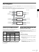
Example 2: When 3D system Presenter microphone Host microphone Chapter 1 Overview MIC/LINE Right camera MIC/LINE Left camera CD/DVD player HD SDI (L) Multi Viewer display HD SDI (R) Right camera LINE Left camera DVI-D DVI⇔HDMI conversion cable HD SDI (L) HD SDI (R) PGM monitoring display Headphones HD SDI (PGM L, PGM R) HD SDI (L+R) PGM PA, etc. For details on configurations for 3D systems, see “Chapter 6: 3D System” (page II-40).
Video Switching Setting the Transition Type This unit allows you to apply various effects when switching video, and compose images using keys. Adjustments and configurations during video switching are performed from the following menus. Menu Description Reference page Misc Set general transition settings (e.g., transition rates, color backgrounds). II-8 Effect Set the transition type. II-7 Set the wipe. II-10 Set the DME wipe. II-13 Set the key.
General Transition Settings ([Misc] menu) You can set the transition rate and the color background (ColBg) with the items in the [Misc] menu. Press the MISC button in the menu control block to display the [Misc] menu. Chapter 2 Video Switching Menu item Description Transition You can set the time (transition rate) it takes to switch Rate (1/2) videos when a transition is executed with the AUTO TRANS button, KEY TRANS button, or FTB button for each transition.
Bus Delegation This unit includes three video composition blocks, M/E (Mix/Effect), Aux1, and Aux2. Each block includes four or two buses and can execute transitions. However, Aux1 is dedicated to Aux1 PGM bus and Aux1 PST bus mixing, Aux2 is dedicated to Aux2 PGM bus and Aux2 PST bus mixing, and wipes, keys, and other effects cannot be added to either.
Mixing operation 1 Press the AUX 1 bus delegation button. 2 Select a PGM in the PGM cross-point buttons. 3 Select the signal you want to mix in the PST/KEY cross-point buttons. 4 Execute the transition using the fader lever, CUT button, or AUTO TRANS button. Chapter 2 Video Switching Tip Aux1 and Aux2 settings are not stored in snapshots.
Selecting the Pattern and Direction for Wipes Setting the wipe position The wipe position can be set in the [Wipe Modify] menu or with the X-Y pointer in the menu control block. A wipe can be set to proceed in either the normal wipe direction (normal) or reverse wipe direction (reverse). You can also specify normal and reverse to be switched each time a transition finishes (normal/reverse).
Setting the aspect ratio of a wipe pattern You can freely change the aspect ratio of a wipe pattern. Adding the Edge to the Wipe Pattern You can add a border around the pattern (border), defocus the edge around the pattern (soft), and defocus an added edge of border (soft border). The edge color can also be adjusted.
Setting DME Wipes This section describes DME wipe effects and basic operations for DME wipes. DME wipe settings are made in the [Effect] menu. You can adjust the position of a DME wipe pattern, adjust the size of the sub-screen for during PinP, perform cropping to cut the edge of the image, and make other settings in the [DME Wipe Modify] menu. To display the [DME Wipe Modify] menu Display the [Effect] menu, turn the V1 knob to select [DME Wipe Adjust], and press this knob.
The cropping process when the transition is executed is as follows. Transition Crop Adding an Edge to a DME Wipe Pattern With a DME wipe, you can add a border around the pattern (border) and defocus the edge of an added border (soft border). The edge color and background color can also be adjusted. y (%) 100 For details on how to add an edge, see “Adding the Edge to the Wipe Pattern” (page II-12).
Details on [Effect] Menu [Effect] Menu Press the EFF button in the menu control block to display the [Effect] menu. Knob Parameter Meaning Setting range Effect Transition V3 1 to 999 frames (30) Wipe Adjust Set the transition rate and transition type that is used when you perform effect transitions. V4 Set the wipe direction and wipe pattern. V1 You can also press the V1 knob to display the [Wipe Modify] menu (page II-16).
Chapter 2 Video Switching Menu item Description Knob Parameter Meaning Setting range DME Wipe Add a border around the DME pattern Edge (border), and defocus the edge of an added border (soft border). V2 Type DME wipe edge type V3 Width V4 Soft V2 Lum Adjusts border width Defocus condition for edge Luminance Off, Border, S-Brdr (soft border) 0.00 to 100.00 (2.00) 0.00 to 100.00 V3 Sat Saturation V4 Hue Hue DME Wipe Adjust the background color for the DME V2 Bkgd Color wipe.
Menu item Description Knob Parameter Meaning Set the rotation method of a wipe pattern. V4 Rotate Rotation type Rotation Adjust Set the parameters depending on the V2 rotation type selected in [Rotation]. • When [Angle] is selected: Set [Angle]. • When [Speed] is selected: Set [Speed]. • When [Mag] is selected: Set [Angle] and [Mag].
[DME Wipe Modify] Menu Display the [DME Wipe Modify] menu by pressing the V1 knob while [DME Wipe Adjust] is selected. Menu item Description Knob Parameter Meaning Setting range Positioner V4 Turn the positioner for adjusting the DME wipe position on/off. Reference page II-13 Pos Turns positioner on/off Off, On Pos H Adjusts position in horizontal direction V3 Pos V Adjusts position in vertical direction V4 Center –200.00 to +200.00 II-13 (0.
Setting Keys Basic Operations for Keys Use the following procedure to perform basic operations for keys. A key is a function for cutting out the background image and then inserting an image or text in that portion. The signal for cutting out the background is called a key source, the signal for filling the cutout portion is called a key fill, and the block for processing a key is called a keyer. With this unit, you can make the following settings for keys.
j Transition execution Execute the transition using the fader lever, CUT button, or AUTO TRANS button. Key transition Selecting the Pattern and Direction for Key Wipes You can cut out the background from a wipe pattern selected for a key transition and then embed a key. Settings menu: [Key Wipe Modify] (page II-24) Material selection For details on the wipe directions, see “Selecting the Pattern and Direction for Wipes” (page II-11). Chapter 2 Video Switching Press the KEY bus delegation button.
Making Detailed Adjustments to Key DME Wipe Patterns Making Detailed Adjustments to the Linear Key You can adjust the position of a key DME wipe pattern and adjust the size of a sub-screen for during Frame In/Out and PinP in the [Key DME Wipe Modify] menu. You can make detailed adjustments for the cutout condition of the background, the key density, and other settings for composing video with linear keys.
The key fill and key source pairs selected when [Auto] is selected are as follows. Key fill Key source Frame memory video Frame memory key Black video White video1) Signals other than the above Same signal as key fill 1) If you perform keying with white video as the key source, the key fill video will fill the entire screen. Setting modifiers for the key edge Turn drop mode on or off and set the type of modifier.
Details on [Key] Menu [Key] Menu Press the KEY button in the menu control block to display the [Key] menu. Description Key Transition Set the transition rate and transition type V3 used when key transition is executed with V4 the KEY TRANS button. Rate Type Transition rate Transition type Key Type Select Select the key type to cut off the images.
Menu item Description Knob Parameter Meaning Dens Key density 0 to 100.00 Reference page – Clean Turns clean mode on/off Off, On – V1 Auto Press the knob to display the [Auto Chromakey] menu – Operating Instructions (Basic Operation) V1 Manual – II-21 V4 Invert Press the knob to display the [Manual Chromakey] menu Turns key source inversion on/off Press the knob to display the [Key Wipe Modify] menu Key wipe direction Off, On – – II-20 Lin Key Adjust the linear key density.
Menu item Description Knob Parameter Meaning Setting range Key Mask Set the key mask function for masking a portion of a key signal. V3 Mask Off, On V4 Invert V3 Left V4 Right V3 Top V4 Bottom Key Mask Box H Key Edge Type Specify the top and bottom positions of the mask box. Turn drop mode on or off and set modifier V3 for the key edge. V4 Border Adjust Adjust the density and width of the border. Border Matte Adjust Adjust the color of the border matte.
[Resizer] Menu Display the [Resizer] menu by pressing the V1 knob while [Resizer] (page II-23) is selected. Menu item Description Knob Parameter Meaning Setting range Rotation Mode Select whether the resizer function moves in 2D or 3D. V3 Axis X, Y V4 Enable Location Depending on this setting, the adjustment ranges for the following [Location], [Aspect], and [Rotation] settings will vary. Reduce/enlarge and move the key.
Menu item Description Knob Parameter Meaning Setting range Rotation V2 • Rotate the key and adjust perspective. Rot X Amount of X-axis rotation • Rot Y Amount of Y-axis • rotation • V4 Pers Perspective • • Chapter 2 Video Switching V3 Reference page When [Rotation – Mode] is [Off], fixed at 0.00 (adjustment is disabled) When [Rotation Mode] is [On], –100.00 to +100.00 (0.00) When [Rotation Mode] is [Off], fixed at 0.00 (adjustment is disabled) When [Rotation Mode] is [On], –100.
[Manual Chromakey] Menu Display the [Manual Chromakey] menu by pressing the V1 knob while [Chromakey Manual Adj] (page II-24) is selected. Chapter 2 Video Switching Menu item Description Knob Parameter Meaning Setting range Chr Key Adjust (1/2) V2 Hue V3 Clip 359.99 to 0.00 (0.00) 0.00 to 100.00 (50.00) V4 Gain V4 Dens Chr Key Adjust (2/2) Color Cancel Color Cancel Adjust Chr Key Window Adjust the background cutout condition, outline sharpness, and other settings.
[Key Wipe Modify] Menu Display the [Key Wipe Modify] menu by pressing the V1 knob while [Key Wipe] (page II-24) is selected. Menu item Description Positioner Knob Parameter Meaning AutoCT Pos Turns auto Off, On center function on/off Turns positioner Off, On on/off Reference page – Tip Positioner Adjust Rotation Rotation Adjust The patterns for which the positioner can be used are as follows. 17, 18, 21, 22, 23, and 24 Adjust the key wipe position. If you want V2 to reset the setting value to “0.
Menu item Description Knob Parameter Meaning Setting range Aspect V3 Aspect Off, On V4 Ratio Turns aspect adjustment on/ off Adjusts aspect ratio V4 Multi Off, On II-12 V2 H Mult 1 to 63 II-12 V3 V Mult V4 InvTyp Turns multi function on/off Number of patterns to place in horizontal direction Number of patterns to place in vertical direction Pattern placement method Multi Chapter 2 Video Switching Multi Adjust Change the aspect ratio of a key wipe pattern.
Audio Mixing Chapter 3 Overview To display the [Audio Channel] menu Press the ACCESS/PFL button in the same column as the channel fader assigned to the audio channel you want to adjust. Chapter 3 Audio Mixing You can adjust the audio input in detail, set the audio levels, and specify the connectors to use for audio output for each audio channel. Adjust and set the audio from the [Audio Channel] menu for each audio channel.
Menu item Description Knob Parameter Meaning Setting range Reference page Equalizer High Use the equalizer function to adjust the audio quality by setting the high-frequency band. V2 EQ H Turns audio quality adjustment of high-frequency band on/off Off, On – V3 Freq Center frequency 1.30 k to of high-frequency 17.40 k (4.75 k) band (kHz) V4 Level Level of high-frequency band V2 EQ M Turns audio Off, On quality adjustment of middle-frequency band on/off V3 Freq Center frequency 260.
Menu item Description PGM Assign Output the audio from the PGM OUT Connector. Knob Parameter Meaning Setting range Reference page V4 PGM Turns output of the PGM OUT connector on/off Off, On – Tip The output level of the audio output from the PGM OUT connector can be adjusted with the program fader in the audio control block. Output the audio from the MIX OUT Connector. V4 MIX Turns output of MIX OUT connector on/off Off, On – AUX1 OUT Assign Output the audio from the AUX OUT 1 connector.
Input Image Freezing and Frame Memory Chapter 4 Input Image Freezing and Frame Memory II-34 Chapter 4 Overview Freezing Input Images Input freeze is a function that allows you to freeze images from individual input signals. 1 Press the FM button in the menu control block to display the [Frame Memory] menu, and turn the V1 knob to select [Input Freeze]. 2 Turn the V3 knob to select the input signal, turn the V4 knob to select [On], and press the V4 knob at the timing you want to freeze.
Selecting Frame Memory for Use as Frame Memory Video (FM) Display the [Frame Memory] menu, turn the V1 knob to select [Select], and turn the V4 knob to select the frame memory to which the image you want to use as the frame memory video is saved. Frame Memory 1 to 12 are indicated as “FM1,” “FM2,” ... “FM12.” Saving Images to Frame Memory Select the frame memory to which to save (Frame Memory 1 to 12), select the input signal to be used as the source, and then freeze the input image to write it to memory.
Tips Importing and Exporting Images • If you import TGA files or TIFF files that include alpha channels, a frame memory that includes a key source will be created. • You can import RLE-compressed TGA files. • Compressed TIFF files cannot be imported. • If you import BMP files, or TGA or TIFF files that do not include alpha channels, a frame memory with an all-white key source will be created.
Importing and Exporting Files Importing and Exporting Configuration Data You can export configuration data in which various settings of the unit have been saved to a USB flash drive, and import saved configuration data to the unit. Tip Note The following settings are not saved under configuration data.
Importing Configuration Data 1 Insert the USB flash drive that stores the configuration data you want to restore into the USB connector of the unit. 2 Display the [File] menu, turn the V1 knob to select [Import Config], and press this knob. The data in the USB flash drive is read and the configuration data that can be imported is displayed. 3 Turn the V1 knob to select the configuration data to import, and press the V4 knob to start importing.
Importing Snapshots Formatting a USB Flash Drive 1 Insert the USB flash drive that stores the snapshots you want to import into the USB connector of the unit. 2 Display the [File] menu, turn the V1 knob to select [Import Snapshot], and then press the knob. 1 Insert the USB flash drive into the USB connector of the unit. The data in the USB flash drive is read and the snapshots that can be imported are displayed.
3D System Chapter • The connectors that can be used for 3D video input and the cross point buttons to which video signals can be assigned are fixed as shown below. Overview With this unit, you can create a 3D video signal by inputting a video for the left eye (L) and a video for the right eye (R) as a pair. This chapter describes the connections and settings required for using the unit in a 3D system.
Making the Necessary Settings Make the settings for operating the unit in a 3D system in the [Setup] menu. Display the [Setup] menu by pressing the SETUP button in the menu control block. Turning 3D Mode On 1 2 Display the [Setup] menu, select [System] menu > [3D Mode], turn the V4 knob to select [On]. Knob Parameter Meaning V4 3D Setting Value Turns 3D mode on/off Off, On Press the V4 knob. A message prompting you to restart the unit appears.
[File] menu Menu item Restriction Import Snapshot • Movement to the sub-level setting is disabled. Export Snapshot • Exporting is disabled. • The following data will not be saved by the [Startup Define] operation in the [Setup] menu. These settings will return to default values at each startup. – PGM bus cross-point: 1 – PST bus cross-point: 1 – Effect transition rate: 30 Confirming 3D Video Output 3D video input is assigned to the cross point buttons (PGM buttons and PST/KEY buttons) 1 and 2.
Controlling External Devices Enabling/Disabling Operation from External Devices Enable or disable the GPI port which is used for operation from external devices. 1 Display the [Misc] menu, turn the V1 knob to select [Port Enable], and use the V3 knob to make the setting. Knob Parameter Meaning V3 GPI Setting range Enables/disables Enbl (enable), GPI port Disbl (disable) Set up a connection with an external device in [GPI/Tally] of the [Setup] menu.
Fall: The trigger causes the output to decrease to a high level, and that status will continue for a certain duration (1 to 2 frames). Any: Every time the trigger is activated, the output’s high and low levels change alternately. If the GPI outputs are used as tallies, the relationship between Tally 1 to 8 and the input signals is as follows.
Menu item Description Knob Parameter Meaning Setting range GPI Input 4 Set the operation and trigger type of the GPI input 4 contacts.
Menu item Description Knob Parameter Meaning GPI Output/ Tally 5 V2 Use Selects whether Tally, GPIOut to use as tally or (GPI output) GPI output V3 Action Operation when used as GPI output NotUse, CT, AT, KeyCT, KeyAT, Aux1CT, Aux1AT, Aux2CT, Aux2AT V4 Edge Trigger type when used as GPI output NotUse, Rise, Fall, Any V2 Use Selects whether Tally, GPIOut to use as tally or (GPI output) GPI output V3 Action Operation when used as GPI output NotUse, CT, AT, KeyCT, KeyAT, Aux1CT, Aux1AT, Aux
Setup ([Setup] Menu) Chapter 8 Overview System Setup (System) Set up the overall system in the [Setup] menu. Make system related settings in the items of the [Setup] menu > [System] menu. The [Setup] menu contains the following items. Description Reference page Startup Define Save the current setup data. Basic Operation System Make system related settings. II-47 Audio Make audio related settings. II-49 Video (Input) Make video input related settings.
Details on [System] Menu Menu item Description Knob Parameter Meaning Setting range System Format V3 108059, 108050, 720p59, 720p50, 480i59, 576i50, Test1, Test2, Test3 16:9, 4:3 Necessary Set the format and aspect ratio to be used by the unit.
Audio Setup (Audio) Assign audio signal inputs to channel faders and make audio related settings in the items of the [Setup] menu > [Audio] menu. SDI output embedded audio and audio signal combinations The following table shows the possible combinations for output. Embedded Audio Possible Combinations for Output SDI 1 to 4 (L) PGM-L MIX-L AUX1 AUX2 AUX1 AUX2 AUX1 AUX2 None None SDI 1 to 4 (R) PGM-R MIX-R AUX1 AUX2 AUX2 AUX1 None None AUX1 AUX2 Tip PGM and MIX are handled as a pair.
Menu item Description SDI OUT AUX1 Assign Knob Parameter Meaning Assign the audio signals output from PGM OUT/MIX V3 OUT/AUX OUT 1/AUX OUT 2 connectors to the embedded audio output from the AUX 1 connector of SDI OUT.
Video Input Setup (Video (Input)) Make video input related settings in the items of the [Setup] menu > [Video (Input)] menu. About DVI input signals • Set the resolution of the DVI signal to be input to one of the following in accordance with the setting of the signal format of the unit (page II-48). Normal images may not be obtained with other resolutions. Analog Digital Signal Resolution 1080i/59.94, 1080i/50 720p/59.94, 720p/50, 480i/59.
Shift button function: Off (non-shift mode) Assigning Video Input Signals to the Cross Point Buttons (Video (XPT)) 1 Assign video signals to the cross point buttons (PGM buttons and PST/KEY buttons) in the items of the [Setup] menu > [Video (XPT)] menu. 2 3 4 5 6 7 8 Shift button function: On (shift mode) For details on the setting procedure, see “Assigning Video Signals to the Cross-Point Buttons” (c Basic Operation). 1 8 Tip In 3D mode, this menu is not displayed.
Video Output Setup (Video (Output)) Set the video output signal to assign to each video output connector in the items of the [Setup] menu > [Video (Output)] menu. Tip In 3D mode, this menu is not displayed. Details on [Video (Output)] Menu Menu item Description Knob Parameter Meaning Setting range SDI OUT PGM Assign V4 Output Output video signal PGM, PVW, Aux1PG, Aux1PV, Aux2PG, Aux2PV, MV Select the signal to assign to the SDI OUT PGM connector.
Setup of Other Video Related Items (Video (Misc)) Make other settings related to videos in the items of the [Setup] menu > [Video (Misc)] menu. Details on [Video (Misc)] Menu Menu item Description Knob Parameter Meaning Switch Timing V4 Timing Switching timing Any (fastest field that can be processed), Field1 (first field), Field2 (second field) V4 Button Enables/disables Enbl (enable)/Disbl FTB button (disable) Set the timing for switching videos.
Appendix Message example: Message List Message type When a problem occurs on the unit during operation, the following types of messages appear. Before contacting your local Sony representative, view the following lists and check the possible solutions. If the problem persists, write down the message number that appears and contact your local Sony representative. 0001 Rate 30 SS File Mon PGM 4203 Message ID USB memory is not recognized. Confirm the USB memory.
ID Message Solution 4203 USB memory is not recognized. Confirm the USB memory. 4204 Formatting USB memory error. Please retry. Check whether operation has been verified with the respective USB flash drive model. If operation has been verified, the USB flash drive may be damaged. 4205 Reading folder/file error. Confirm the folder/file. 4206 Making folder/file error. Please retry. 4207 Importing error. Please retry. 4208 Exporting error. Please retry.
Information ID Message Solution 1101 The setting is changed. Perform "Startup Define", and then restart. This appears when you change the system format or 3D mode, or when the system otherwise needs to be restarted. Execute [Startup Define], and restart the unit. 1102 Finished. Please restart.
AUX OUT Assign II-33 Index Numerics 3D Mode II-41, II-48 3D System II-40 8/SHIFT I-11 A Index II-58 ACCESS/PFL Button I-9, I-33, II-31 Adjustment Knobs 1 to 4 I-10 Incremental Adjustment I-11 Aspect II-17, II-26, II-30 Aspect Ratio I-17 Audio I-21, I-32 Mixing I-32 Monitoring I-33 Audio Channel Menu II-31 AUX OUT Assign II-33 Equalizer High II-32 Equalizer Low II-32 Equalizer Mid II-32 Filter II-31 Input Trim II-31 Limiter/Compressor II-32 MIX OUT Assign II-33 Pan II-32 PGM Assign II-33 Audio Control B
Fine Key Adjust V II-25 Flip Tumble I-37 FM Button I-10, II-34 Formatting USB Flash Drive II-39 Frame In/Out I-26, I-37 Frame Memory II-34 Frame Memory Freeze II-35 Frame Memory Menu II-34, II-35, II-36 Export II-36 Frame Memory Freeze II-35 Import II-36 Input Freeze II-34 Select II-35 Freezing II-34 Front Panel I-9 FTB Button I-11, II-8, II-54 G GPI Input I-42, II-43, II-44 GPI Output I-42, II-43 GPI Output/Tally II-45 GPI/Tally Menu II-44 GPI Input II-44 GPI Output/Tally II-45 On Air Source II-46 H HDMI
O On Air Source II-46 Oscillator II-50 Output Level II-50 P Pan II-32 Peak Indicator I-9, I-22 PFL I-33 PGM Assign II-33 PGM Cross-Point Button I-11, I-19, I-25 Pin Configurations I-42 PinP I-37, II-13 Port Enable II-8 POS Button I-10, II-11, II-13 Positioner II-16, II-18, II-29 Positioner Adjust II-16, II-18, II-29, II-30 Pre-Fade Listen I-33 Preview Video I-23 Program Fader I-9, I-32 Program Video I-23 PST/KEY Cross-Point Button I-11, I-19, I-25 R REF OUT Phase II-48 Reference Signal Input/Output Block
XPT Shift Mode II-52 X-Y Pointer I-10, II-11, II-13 Index Index II-61
The material contained in this manual consists of information that is the property of Sony Corporation and is intended solely for use by the purchasers of the equipment described in this manual. Sony Corporation expressly prohibits the duplication of any portion of this manual or the use thereof for any purpose other than the operation or maintenance of the equipment described in this manual without the express written permission of Sony Corporation.
Sony Corporation