3-858-309-14(1) Digital Videocassette Recorder Operating Instructions Before operating the unit, please read this manual thoroughly and retain it for future reference.
Owner’s Record For the customers in the USA The model and serial numbers are located at the rear. Record the serial number in the space provided below. Refer to these numbers whenever you call upon your Sony dealer regarding this product. This equipment has been tested and found to comply with the limits for a Class A digital device, pursuant to Part 15 of the FCC Rules.
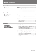
Table of Contents Chapter 1 Overview Features ............................................................................. 5 Location and Function of Parts ....................................... 8 Front Panel .......................................................................... 8 Rear Panel ......................................................................... 14 Chapter 2 Recording and Playback Recording ........................................................................
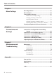
Table of Contents Chapter 4 Menu Settings Menu Organization .......................................................... 41 Menu Contents ................................................................ 42 Changing Menu Settings ................................................ 51 Buttons Used to Change Settings ...................................... 51 Changing the Settings of Basic Items ............................... 51 Displaying Enhanced Items ...............................................
Features Wide track pitch The recording track pitch is 15 µm, fully 50 percent wider than the DV format’s 10-µm track pitch. Thanks to this feature, the DVCAM format sufficiently meets the reliability and precision requirements of professional editing. High-quality PCM digital audio PCM recording makes for a wide dynamic range and a high signal-to-noise ratio, thereby enhancing sound quality.
Features A Wealth of Interfaces Chapter 1 Overview Digital interfaces The unit provides the following two digital interfaces. • SDTI (QSDI)1): This interface enables SDTI (QSDI)format video, audio and time code signals to be transferred between this unit and the Sony EditStation either at normal speed or four times normal. • AES/EBU interface: This interface enables AES/ EBU-format digital audio signals to be input and output.
Easy maintenance functions Using the frame memory function, the unit can show noise-free slow-motion playback at speeds ranging from 0 to 1/5 normal in both directions. Frame-byframe and field-by-field playback modes are also available. • Self-diagnostic/alarm function: This function automatically detects setup and connection errors, operation faults, and other problems.
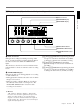
Location and Function of Parts Location and Function of Parts Front Panel Chapter 1 Overview 1 Display section (A) and video/audio input setting section (see page 9) 2 Display section (B) and COUNTER SELECT button (see page 11) 1 Cassette compartment 2 REMOTE/LOCAL switch 3 POWER switch 4 HEADPHONES control knob 5 HEADPHONES connector 6 0 ) p r 6 CONTROL S connector 3 Tape transport control section (see page 12) 4 Menu control panel (inside of the door) (see page 13) 1 Cassette compartment Ac
1 Display section (A) and video/audio input setting section 1 Audio level meter Chapter 1 Overview 2 AUDIO MODE display 3 INPUT MODE display OVER dB 0 OVER dB 0 OVER dB 0 OVER dB 0 AUDIO MODE INPUT MODE AUDIO CH-1,1/2 CH-2,3/4 COMPOSITE ANALOG ANALOG VIDEO -12 -12 -12 -12 -20 -20 -20 -20 -30 -40 -30 -40 -30 -40 -30 -40 -60 CH-1 -60 CH-2 -60 -60 CH-3 2CH Fs48k Fs44.
Location and Function of Parts Chapter 1 Overview 3 INPUT MODE display Indicates the format of the currently selected video and audio input signals. VIDEO indicators: The corresponding indicator lights when the selected video input signal is in the composite analog, S-video, component analog, or SDI (serial digital interface) format.
2 Display section (B) and COUNTER SELECT button 1 COUNTER SELECT button Chapter 1 Overview 2 Time data type indicators 3 Time counter display 4 Tape end alarm indicator COUNTER TC U-BIT HOURS REMOTE EDIT MODE COUNTER SELECT EJECT REW 6 0 MINUTES SECONDS 4 FRAMES NOT EDITABLE CIip Link PLAY REC INHIBIT F FWD STOP REC ) p r 5 REC INHIBIT indicator 6 NOT EDITABLE indicator 7 Cassette memory indicator 8 ClipLink indicator 9 × 4 indicator 0 EDIT MODE indicator !¡ REMOTE indicator 1 COUN
Location and Function of Parts 8 ClipLink indicator Lights when a cassette is loaded on which ClipLink log data is stored in the cassette memory. 0 EDIT MODE indicator Lights when this unit is selected as the recorder VCR under the control of an editing controller connected to the REMOTE connector on the rear panel of the unit. Chapter 1 Overview For details of ClipLink log data, refer to the “ClipLink Guide” also supplied with this unit.
4 Menu control panel Chapter 1 Overview The menu control panel is located on the inside of the door at the lower front of the unit. Press on the top of the door to open it. To expose the menu control panel PUSH OPEN 1 SYNC PHASE control 2 SC PHASE control Press on the top of the door.
Location and Function of Parts Chapter 1 Overview 8 MONITOR SELECT switches Use these switches to select the channels for audio output via the MONITOR AUDIO connector on the rear panel and the HEADPHONES connector on the front panel. Use the left switch to select the basic channel setting, then use the right switch to select the output format (monaural, stereo, or mix). The table at right lists the correspondence of left/right switch settings and channel/output format selections.
1 Analog video signal input/output section ANALOG VIDEO IN VIDEO OUT 1 IN 75Ω ON 1 REF. VIDEO IN connectors and 75 Ω termination switch 75Ω ON OFF OUT 6 VIDEO OUT 1 and 2 (SUPER) connectors OFF IN 2 REF. VIDEO OUT connector 3 TIME CODE IN connector 2 (SUPER) COMPONENT VIDEO OUT Y 7 COMPONENT VIDEO IN connectors TIME CODE IN R-Y 8 COMPONENT VIDEO OUT connectors OUT 4 TIME CODE OUT connector B-Y 9 S VIDEO IN connector S VIDEO MONITOR AUDIO IN OUT 0 S VIDEO OUT connector 1 REF.
Location and Function of Parts 9 S VIDEO IN connector (4-pin) Input an S-video signal with separated Y (luminance) and C (chroma: 3.58 MHz for DSR-85 and 4.43 MHz for DSR-85P) components. 0 S VIDEO OUT connector (4-pin) Outputs an S-video signal with separated Y (luminance) and C (chroma: 3.58 MHz with DSR-85 and 4.43 MHz with DSR-85P) components.
3 SDI (Serial Digital Interface) signal input/output section (with the optional DSBK-120/ 120P installed) Chapter 1 Overview When an optional DSBK-120/120P SDI Input/Output Board is installed in the unit, this section can be used for inputting and outputting SDI signals.
Location and Function of Parts 4 Analog audio signal input/output section ANALOG Chapter 1 Overview REF.
Recording Settings for Recording 1 6 Video monitor REMOTE/LOCAL switch ) 0 p 2 Player (DSR-60/60P, etc.) Audio level meter AUDIO MODE display INPUT MODE display 3 6 7 6 5 4 0 ) p r Recorder (DSR-85/85P) Note When controlling this unit from an editing controller, set the REMOTE/ LOCAL switch to “REMOTE”. When not, set the switch to “LOCAL”. 1 Power on the video monitor, then set the monitor’s input switches according to the input signals from this unit.
Recording 4 When the REMOTE/LOCAL switch is set to “LOCAL”, use the COUNTER SELECT button to select the type of time data to be used. Each press of this button cycles through three options: COUNTER (CNT value), TC (time code), and U-BIT (user bit data). The time data type indicator for each option lights as it is selected. When the REMOTE/LOCAL switch is set to “REMOTE”, selection of the time data type is carried out at the editing controller.
6 Select the audio mode. Press the AUDIO REC SELECT button to select the desired mode. Each selection is shown by lit indicators in the AUDIO MODE display. Audio mode Lit indicator in AUDIO MODE display 2-channel mode 2CH and Fs48k 4-channel mode 4CH and Fs32k Cautions 7 Use the AUDIO INPUT LEVEL control knobs to adjust audio input levels. Watching the audio level meter, adjust the level so that the meter does not indicate higher values than 0 dB when the audio signal is at its maximum.
Recording Usable Cassettes This unit can use standard-size and mini-size DVCAM cassettes listed below. Model name Size PDV-64ME/94ME/124ME/184ME Standard size PDVM-12ME/22ME/32ME/40ME Mini size Chapter 2 Recording and Playback The numbers in each model name indicate the maximum recording/ playback time (in minutes) for each model. For example, the PDV-184ME has a maximum recording/playback time of 184 minutes. Notes • If you insert an incorrect type of cassette, it will be automatically ejected.
Notes on using cassettes For instructions on removing tape slack, see page 27. Chapter 2 Recording and Playback 23 Chapter 2 Recording and Playback • Before storing the cassette, rewind the tape to the beginning and be sure to put the cassette in its storage case, preferably on end instead of flat on its side. The storage case of a DVCAM cassette is specially designed to ensure a long-period storage of the tape. Storing a cassette in any other condition (not rewound, out of its case, etc.
Recording Recording Procedure This section describes the procedure to perform a recording on this unit, showing an example session in which playback signals coming from a player VCR will be recorded on the tape loaded in the unit. REMOTE/LOCAL switch 1 Chapter 2 Recording and Playback 6 ) 0 r p 2 Recorder (DSR-85/85P) 3 6 0 ) p Player (DSR-60/60P, etc.) Notes • When controlling this unit from an editing controller, set the REMOTE/ LOCAL switch to “REMOTE”. When not, set the switch to “LOCAL”.
Mini size Insert the mini-size cassette into the middle of the cassette compartment. Standard size The cassette is automatically drawn into the unit and the tape is wound round the head drum. The tape is stationary while the head drum rotates, and the STOP button lights. If the REC INHIBIT indicator lights: It indicates that the loaded cassette’s REC/SAVE switch has been set to SAVE.
Recording If the following indicators light when a cassette is loaded Indicator It means: Cassette memory indicator The loaded cassette contains a cassette memory. ClipLink indicator There is ClipLink log data stored in the cassette memory on the loaded cassette. Caution With such a cassette, execution of recording may destroy the ClipLink log data. NOT EDITABLE indicator Chapter 2 Recording and Playback The recording format of the tape is “DV”.
Preventing accidental erasure Set the REC/SAVE switch on the cassette to SAVE to prevent accidental erasure of recorded contents. REC/SAVE switch Set to SAVE REC SAVE Checking the tape for slack Using a paper clip or a similar object, turn the reel gently in the direction shown by the arrow. If the reel does not move, there is no slack. Insert the cassette into the cassette compartment, and after about 10 seconds take it out. Paper clip, etc.
Playback Playback This section describes the necessary settings and operations to perform playback on this unit. The same settings and operations apply whether you are using the unit as part of an editing system, for dubbing, or as a standalone videocassette player. For the necessary connections for playback and the settings not covered in this section, see Chapter 5 “Connections and Settings”.
Playback Procedure 1 2 REMOTE/LOCAL switch 0 ) p r Note When controlling this unit from an editing controller, set the REMOTE/ LOCAL switch to “REMOTE”. When not, set the switch to “LOCAL”. 1 Insert a cassette. For details of cassette insertion see page 24, and for usable cassette types see page 22. The cassette is automatically drawn into the unit. The STOP button will light, and a few seconds later a still image will appear on the monitor screen. 2 Press the PLAY button.
Playback For this purpose: Stop playback Adjust the audio playback level Search while viewing Do this: Press the STOP button. The unit enters stop mode, and will automatically switch to standby off mode after 8 minutes. Use the audio level control on the monitor. Press and hold either F FWD or REW button to search at 32 times normal speed in forward or reverse direction. To return to normal playback mode, press the PLAY button.
Setting the Time Data When the unit is equipped with an optional DSBK130/130P Time Code Input/Output Board, it can output the time code read from the tape as an analog (LTC) signal while in normal-speed playback mode, and receive an external analog time code (LTC) signal. Note Even when the unit is equipped with the DSBK-130/ 130P, it outputs no signal from the TIME CODE OUT connector unless it is in normal-speed playback mode.
Setting the Time Data C Drop frame indication for time code generator (on DSR-85 only) . Drop frame mode (factory default setting) : Non-drop frame mode To display the desired time data in the time counter display COUNTER SELECT button D DSR-85/85P operation modes CASSETTE OUT STANDBY OFF T. RELEASE STOP F.
For details of menu settings, see Chapter 4 “Menu Settings”. Using the Internal Time Code Generator You can set the time code’s initial value before recording the time code generated by the internal time code generator onto a tape. In addition, you can set the time code’s user bits to record user bit data such as the date, time, scene number, reel number, or other useful information. 3 Press the TC PRESET button on the menu control panel.
Setting the Time Data 7 Press the SET (YES) button. The message “NOW SAVING...” appears on the monitor screen, “Saving...” appears in the time counter display, and the new settings are stored in the unit’s memory. After this saving operation is completed, the monitor screen and the time counter display return to their usual status. Note The set data may be lost if you power off the unit while the above saving operation is in progress. Wait until the saving operation is completed before powering off.
Rerecording the Time Code — TC Insert Function The TC insert function makes it possible to use the internal time code generator to rewrite time code and user bits when the time code recorded on a tape is discontinuous. You can start recording time code from an initial value which can be set freely. (See page 33.
Setting the Time Data 5 8 Press the ÷ button. The following message appears. TC INSERT TC INSERT AT 4 TIMES NORMAL SPEED? Press the SET (YES) button. Time code recording starts. TC INSERT x4 mode? Time counter display X4 : YES KEY X1 : NO KEY ABORT: MENU KEY Executing Time counter display EXECUTING.
High-Speed and Low-Speed Search: Quickly and Accurately Determining Editing Points Use the search function to easily locate the desired scene and to quickly and accurately determine edit points. Search Operations via External Equipment You can control the following operation modes of the unit either from an editing controller (such as the ES-7, PVE-500, etc.
Dubbing Signals in QSDI Format — QSDI Dubbing Dubbing Signals in QSDI Format — QSDI Dubbing Function Function In addition to straightforward tape dubbing, you can also use this unit to dub automatically from the beginning of the tape to the end, through an QSDI interface. When a tape recorded on a DSR-1/1P Digital Videocassette Recorder or DSR-130/130P Digital Camcorder is dubbed, the ClipLink log data held in the cassette memory can also be copied. 1 Press the MENU button on the menu control panel.
5 8 Press the ÷ button. The tape is automatically wound back to the beginning, and dubbing starts. The following message appears. QSDI DUBBING (A/V/TC/CM) DUB AT 4 TIMES NORMAL SPEED? Press the SET (YES) button. x4 mode? QSDI DUBBING (A/V/TC/CM) Time counter display Executing Time counter display EXECUTING.
Dubbing Signals in QSDI Format — QSDI Dubbing Function If the following message appears in step 7 for an A/V/TC/CM dubbing operation QSDI DUBBING (A/V/TC/CM) CM capacity! Time counter display CM MEMORY STORAGE CAPACITY OF THE RECORD TAPE IS TOO SMALL. ABORT:MENU KEY Monitor screen Chapter 3 Convenient Functions for Editing Operation When carrying out A/V/TC/CM dubbing, the contents of the cassette memory of the cassettes inserted in both this unit and the player are checked.
Menu Organization For details of the auto mode execution menu, see the sections “Dubbing Signals in QSDI Format” (page 38) and “Rerecording the Time Code — TC Insert Function” (page 35). For details of the digital clock display, see the section “Regular Checks” (page 69). The items of the setup menu are divided into several functional groups on level 1, and except for the MENU GRADE item the settings themselves are made on level 2 or level 3.
Menu Contents Menu Contents (Examples) SETUP Menu The purpose and settings of the setup menu items are described below. Indications of menu Items and settings • In the table below entitled “Menu Contents”, the indication of each menu item or setting on the monitor screen is shown first, then the indication of the same item or setting on the time counter display of this unit is shown in square brackets ([ ]).
Menu contents (Continued) OPERATIONAL FUNCTION [Operational]: Operation Description of settings settings PREROLL TIME [> Preroll]: Set the preroll time. The preroll time can be set in one-second increments to between 0 and 15 seconds (0 SEC [>> 0 SEC] to 15 SEC [>> 15 SEC]). When an editing controller such as the PVE500 has been connected, this setting is disabled and the editing controller’s setting is in effect.
Menu Contents Menu contents (Continued) DISPLAY CONTROL [Display]: Settings related to Description of settings indications on the monitor and the unit CHARA. TYPE [> Chara type]: Set the type of characters in text superimposed on output from the VIDEO OUT 2 (SUPER) connector to the monitor. Make the following settings while watching the monitor screen.
Menu contents (Continued) DISPLAY CONTROL [Display]: Settings related to Description of settings indications on the monitor and the unit OVER DISP HOLD [> Hold OVER]: Determine whether or not ∗OFF [>> OFF]: Do not hold the OVER indication display. to hold the OVER indication display on the audio level ON [>> ON]: Hold the OVER indication display. meter once the indication lights. Note With “ON” selected, once the display is held it will remain held unless you change the setting to “OFF”.
Menu Contents Menu contents (Continued) TIME CODE [Time code]: Settings related to the time code generator UB BINARY GP. [> UB Binary Gp]: Select the user bit binary group flag of the time code generator Note When the TC MODE menu item is set to EXT REGEN, the user-bit binary group flag setting follows the setting on the time code input to this unit. TC EE OUT MODE [> TC out mod]: This only appears when the optional DSBK-130/130P Timecode Input/Output Board is installed.
Menu contents (Continued) VIDEO CONTROL [Video]: Settings related to video Description of setting control STILL MODE [> STILL mod]: Determine whether the image of a whole frame or a field is output in still playback mode. FRAME STILL [>> Frame]: Output the image of a whole frame. ∗FIELD 1 STILL [>> Field 1]: Output the image of field 1 only. FIELD 2 STILL [>> Field 2]: Output the image of field 2 only. (Only on DSR-85) ∗OFF [>> OFF]: Do not remove black setup.
Menu Contents TC EE OUT MODE settings Use the following as reference information when setting “TC EE OUT MODE” (see page 46). • THROUGH mode In this mode, the LTC signal is output with the phase synchronized to the input timecode signal, and is appropriate when recording signals from multiple devices on a number of VCRs. When the camcorder is in genlock mode the timecode precision is ±0 frames, and when not in genlock mode is ±1 frame.
• VIDEO OUTPUT PHASE mode The timecode output signal is synchronized to the output video signal. This mode is appropriate when the output from a single device is output to a number of VCRs with separate cables for video, audio, and timecode. In this mode, the same timecode is recorded on all of the VCRs 1 to n. VIDEO OUT VIDEO IN AUDIO OUT VIDEO OUT AUDIO IN TIME CODE OUT Input device (VCR, camera, etc.
Menu Contents Auto mode (AUTO FUNCTION) execution menu The following table shows the purpose and function of the items in the auto mode execution menu. For details of the use of individual items, see the sections “Dubbing Signals in QSDI Format” (page 38) and “Rerecording the Time Code — TC Insert Function” (page 35). Menu contents QSDI DUBBING [QSDI dub]: Selection of data for QSDI Description of setting dubbing For dubbing through the QSDI interface, select data that the dubbing applies to.
Changing Menu Settings This section explains how to change menu settings. 1 Press the MENU button on the menu control panel. The menu selection level display appears on the monitor, with “SETUP MENU” selected (shown in reverse video). The time counter display of this unit shows only the currently selected item. When the item name is long, it is abbreviated. Buttons Used to Change Settings Use the following buttons on the menu control panel to change the menu settings.
Changing Menu Settings 4 7 Press the ÷ button. This displays the menu level 2 for the menu item selected in step 3. Example: Level-2 display for “DISPLAY CONTROL” SETUP MENU DISPLAY CONTROL CHARA.DISPLAY :ON CHARA.POSITION CHARA.
Meanings of indications on the monitor screen On-screen indication Meaning Right-pointing arrow at the Pressing the ÷ button right of a menu item (See switches to the next lower menu level or to a setting step 1 on page 51.) selection screen. Left-pointing arrow at the left of a menu item (See step 4 on page 52.) Pressing the ¿ button returns to the previous (higher) menu level. Character string at the right of a menu item (See step 4 on page 52.) Current setting of the menu item.
Changing Menu Settings 4 When you have completed the settings, press the SET (YES) button. The message “NOW SAVING...” appears on the monitor screen, and “Saving...” appears in the time counter display, while the new settings are saved in the unit’s memory. When the saving operation is completed, the monitor screen and time counter display return to their normal indications.
Displaying Supplementary Status Information When you set “SUB STATUS” under the DISPLAY CONTROL menu item to other than “OFF”, you can view supplementary status information on the monitor screen below the operating mode display area. 0 0 : 0 4 . 4 7 . 0 7 T C R P L A Y I N S V L O C K A 1 2 3 4 T C When “SUB STATUS” is set to “TC MODE”: On-screen indication Meaning INT PRESET FREE [IP F] The internal time code generator is operating in FREE RUN mode.
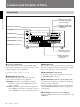
Connections for a Digital Non-Linear Editing System For a general description of ClipLink functions, refer to “ClipLink™ Guide” supplied with the unit. REF. VIDEO IN QSDI INPUT The following figure shows a connection diagram for non-linear editing system in which this unit serves as the recorder. For connections of the ES-7 and its peripheral devices such as the ESBK-7011 Control Panel, the ESBK-7045 Disk Unit, etc., refer to your ES-7 Operating Instructions.
Connections for a Cut Editing System Connections for a Cut Editing For details of connecting devices other than the DSR-85/ 85Ps, refer to the instruction manual for each device. The following figure shows a cut editing system configuration that includes two DSR-85/85Ps to serve as the player and recorder.
Connections for an A/B Roll Editing System The following is an example configuration of A/B roll editing system using the DSR-85/85P. In this configuration, the recorder is a DSR-85/85P, player 1 is a DSR-60/60P, and player 2 is an analog Betacam UVW-1600/1600P Videocasette Player. To create a final tape (a tape that contains a completely packaged program) in Betacam format, you can use a Betacam VCR such as the UVW-1800/1800P as the recorder.
Connections for an A/B Roll Editing System Audio monitor system connections Reference video signal connection The following shows an example of audio monitor system connections. When you perform editing, be sure to use a reference video signal. DFS-500/500P DME Switcher For details of these connections, refer to each connected device’s instruction manual. Speaker (left channel) Speaker (right channel) BLACK BURST OUT 4 3 2 1 REF. VIDEO IN 75 Ω termination switch: ON DSR-85/85P (recorder) REF.
Control signal connections The following shows an example of control signal connections to enable the editing controller to control all other A/B roll editing system devices. DSR-85/85P (recorder) Setting on all devices controlled from the editing controller Switch Setting REMOTE/LOCAL REMOTE REMOTE 9-pin remote control cable a) DSR-60/60P (player 1) ANALOG I/O REF.
Connections for an A/B Roll Editing System Video/audio signal connections The following shows an example of video/audio signal connections in an A/B roll editing system. In this example, analog component signals are used as the video signals and XLR 3-pin connectors are used as audio input/output connectors. 1 COMPONENT VIDEO IN (Y, R–Y, B–Y) DSR-85/85P (recorder) DFS-500/500P DME Switcher VIDEO INPUTS COMPONENT 2 PGM OUT COMPONENT 1 AUDIO IN CH-1 3 CH-1 OUT CH-2 3 CH-2 OUT ANALOG I/O REF.
Connection of a video monitor Settings on an editing control unit Set up the following connections to enable monitoring of video and audio signals on a video monitor. In addition to video signals, you can have time data, the DSR-85/85P’s operation mode, alarm messages, and other information displayed as text on the monitor screen by setting “CHARA. DISPLAY” under the DISPLAY CONTROL menu item to “ON” (this is the factory default setting).
Connections for QSDI Dubbing Connections for QSDI Dubbing The following shows an example of connections for QSDI dubbing (see page 38), with the DSR-85/85P used as the recorder and a DSR-60/60P as the player. (Using a DSR-60/60P for QSDI dubbing requires an optional DSBK-110/110P QSDI Output Board.) DSR-60/60P (player) a) This connector is provided by the optional DSBK-110/ 110P QSDI Output Board.
Connections for Analog Recording The following shows connections for a system in which analog playback signals from another recorder or player are recorded on a DSR-85/85P. In this system, the video signals are analog component signals and the audio signals are recorded from audio channels 1 and 2. Video monitor 1 Cable with RCA phono plugs (not supplied) 2 75 Ω coaxial cable (not supplied) 3 Cable with XLR connectors (not supplied) a) Three 75 Ω coaxial cables are used one each for Y, R–Y, and B–Y.
Adjusting the Sync Subcarrier Adjusting theand Sync andPhases Subcarrier When using two or more players, as in an A/B roll editing system, phase synchronization of the signals (i.e. system sync) is necessary and for composite signals, the subcarrier phase must also be in sync. If not, picture instabilities or color break-up may occur at edit points. Phases After configuring the editing system, use a vectorscope to adjust the sync and subcarrier phase of the recorder and players.
Performing a phase adjustment operation 1 7 Press the SCH button on the vectorscope. The vectorscope switches to “SCH” mode. 2 Press the B channel button on the vectorscope. This indicator moves as you turn the SYNC control. This displays the black burst signal from the switcher. 3 On player 1, adjust the SYNC and SC controls, using a Phillips screwdriver, so that the output from player 1 on channel (A) is in correct phase alignment with the black burst signal on channel (B).
Maintenance If you move the unit suddenly from a cold to a warm location, or if you use it in a very humid place, moisture from the air may condense on the head drum. This is called condensation, and if a tape is run in this state, the tape may stick to the drum and can be easily damaged. To lessen the risk of this occurring, this unit is equipped with a condensation detection system. If condensation occurs while the unit is operating: The alarm message “MOISTURE HAS BEEN DETECTED.
Maintenance 2 Press the ≥ button to select “HOURS METER”. SYSTEM MENU SETUP MENU AUTO FUNCTION HOURS METER Hours meter Time counter display The following illustrates the digital hours meter indications on the time counter display in all four display modes. The right-hand indication for each display mode is the indication you can view while holding down the ÷ button on the menu control panel. T1 (OPERATION) mode: Oper. 00000 3 Monitor screen Press the ÷ button.
Troubleshooting If an alarm message appears on the monitor screen or the time counter display, or if the unit appears to be malfunctioning, please check the following before contacting your Sony dealer. Tape problems Symptom Cause Remedy Recording is not possible. The cassette’s REC/SAVE switch is set to SAVE.a) Set the REC/SAVE switch to REC. The unit’s tape transport The REMOTE/LOCAL switch is set to control buttons (PLAY, F FWD, REMOTE and “LOCAL ENABLE” under REW, etc.) do not work.
Troubleshooting Monitor problems Symptom Cause Data is not superimposed on the monitor screen. “CHARA. DISPLAY” under the DISPLAY Set “CHARA. DISPLAY” to “ON”. (See page 43.) CONTROL menu item is set to “OFF”. Remedy The monitor is not connected to the VIDEO OUT 2 (SUPER) connector of this unit. Connect the monitor to the VIDEO OUT 2 (SUPER) connector. (You must make this connection to display any type of text on the monitor.) The image on the monitor’s screen is too bright.
Error Messages This unit is provided with a self-diagnostic function that detects internal abnormalities. When it detects an abnormality, it outputs an error message to the monitor screen and indicates an error code in the time counter display. If an error message appears, follow the direction indicated under the message in the monitor screen. Note To display error messages on the monitor screen, it is necessary for the monitor to be connected to the VIDEO OUT 2 (SUPER) connector, and for “CHARA.
Troubleshooting List of alarm messages and associated directions Here is a list of alarm messages and associated directions to appear on the monitor screen. It also shows the corresponding alarm messages to appear on the time counter display of this unit. Alarm message on monitor screen In this list the “Causes” of alarm are arranged in alphabetic order of the first word of their phrases.
Alarm messages and associated directions (Continued) Alarm message on monitor screen Direction Alarm message on time counter display Key is jammed. Check the following buttons: EJECT, STOP, F FWD, REW, PLAY, REC, ˘, ≥, ¿, ÷, SET (YES), TC PRESET, MENU, RESET (NO), INPUT SELECT (VIDEO, AUDIO CH-1 CH-1/2, AUDIO CH-2 CH-3/4, QSDI), COUNTER SELECT, AUDIO REC SELECT Key jammed! Moisture has been detected. Keep the power on and wait until this alarm message disappears. HUMID! No cassette in VTR.
Notes on Use Appendix Appendix Operation and storage locations Avoid operation or storage in any of the following places. • Location subject to extremes of temperature (operating temperature range 5°C to 40°C (41°F to 104°F)) • Location subject to direct sunlight for long periods, or close to heating appliances (Note that the interior of a car left in summer with the windows closed can exceed 50°C (122°F).
Specifications Specifications Tape speed DSR-85: 28.193 mm/s DSR-85P: 28.
Audio performance Input connectors Digital signal inputs QSDI INPUT BNC type, QSDI format (270 Mbps) SDI INPUT (with optional DSBK-120/120P SDI Input/Output Board installed) BNC type (×2, active-through), Serial Digital Interface format (270 Mbps), SMPTE 259M/ CCIR656-III Analog video inputs REF. VIDEO IN BNC type (×2, loop-through), black burst, 0.286 Vp-p, 75 Ω, sync negative VIDEO IN BNC type (×2, loop-through), composite, 1.0 Vp-p, 75 Ω, sync negative COMPONENT VIDEO IN BNC type (×3), component Y: 1.
Specifications Appendix Analog audio outputs AUDIO OUT XLR 3-pin, male (× 4), +4 dBu, 600 Ω loading, low impedance, balanced MONITOR AUDIO Phono jack, –6 dBu +1 dBu/–1 dBu 47 kΩ, unbalanced Digital audio outputs DIGITAL AUDIO (AES/EBU) OUTPUT XLR 3-pin, male (×2), 110 Ω, balanced Output for headphones HEADPHONES Stereo phone jack, –16 dBu +2 dBu/–2 dBu, 8 Ω, unbalanced Time code output TIME CODE OUT (with optional DSBK-130/130P Time Code Input/Output Board installed) BNC type, SMPTE time code (DSR-85), EB
Glossary B–Y signal A chrominance signal determined by subtracting the Y (luminance) signal from the B (blue) signal. One of the component signals. Capstan A drive mechanism that moves the tape at a specified speed. Its rotation normally synchronizes with a reference sync signal. Chrominance signal Color signal containing color information such as hue and saturation. Also called C signal. Component signal A video signal consisting of a luminance signal (Y) and two chrominance signals (R–Y, B–Y).
Glossary S-video A signal format in which Y (luminance) and C (chrominance) signals are separated to reduce interference between them so that noiseless images are reproduced. Appendix Sync signal A reference signal consisting of vertical and horizontal sync signals used for synchronizing the scanning patterns of the video camera and the monitor. TBC Abbreviation of Time Base Corrector.
Index A B BRIGHTNESS (menu) .......................... 45 B–Y signal input .................................... 16 B–Y signal output .................................. 16 Care ....................................................... 77 Cassette compartment .............................. 8 Cassette memory indicator .................... 11 Cassette memory ............................. 11, 22 Cassettes ................................................ 22 inserting ...........................................
Index Internal time code generator/ reader ............................... 6, 33, 34, 35 advancement .................................... 34 using ................................................ 33 J, K Jog audio, search ................................... 37 Jog ......................................................... 37 L Index LOCAL ENABLE (menu) ..................... 42 Luminance signal input ......................... 15 Luminance signal output ....................... 15 M Maintenance ...........
Index TIME CODE IN connector ................... 15 TIME CODE OUT connector ............... 15 Time code reader ..................................... 6 Time code .............................................. 31 initial value, setting ......................... 33 rerecording ...................................... 35 synchronizing ............................ 33, 34 Time counter display ............................. 11 Time data problems ............................... 71 Time data type indicators .........
Sony Corporation Printed in Japan