
VCR Operating Instructions DSR-85, 85P
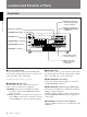

Location and Function of Parts
Chapter 1 Overview
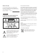
10 Chapter 1 Overview
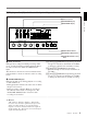
3 INPUT MODE display
Indicates the format of the currently selected video and
audio input signals.
VIDEO indicators: The corresponding indicator
lights when the selected video input signal is in
the composite analog, S-video, component analog,
or SDI (serial digital interface) format.
AUDIO CH-1, 1/2 indicators: The ANALOG, AES/
EBU or SDI indicator lights for the corresponding
format of the selected audio signal being input to
channel 1 (when in 2-channel mode) or to
channels 1 and 2 (when in 4-channel mode).
AUDIO CH-2, 3/4 indicators: The ANALOG,
AES/EBU, or SDI indicator lights for the
corresponding format of the selected audio signal
being input to channel 2 (when in 2-channel
mode) or to channels 3 and 4 (when in 4-channel
mode).
QSDI: Lights when QSDI-format video and audio
input signals have been selected. When QSDI is
selected, all of the indicators in the VIDEO and
AUDIO groups go off.
4 INPUT SELECT buttons
Select video input signals and audio input signals.
VIDEO button: Each press of this button cycles
through four video signal selection options:
composite analog, S-video, component analog,
and SDI. When you select one of these options,
the corresponding VIDEO indicator in the INPUT
MODE display lights up.
AUDIO CH-1, CH-1/2 button: Each press of this
button cycles through three audio signal selection
options for audio channel 1 (when in 2-channel
mode) or channels 1 and 2 (when in 4-channel
mode): analog, AES/EBU, and SDI. When you
select one of these options, the corresponding
AUDIO indicator in the INPUT MODE display
lights up.
AUDIO CH-2, CH-3/4 button: Each press of this
button cycles through three audio signal selection
options for audio channel 2 (when in 2-channel
mode) or channels 3 and 4 (when in 4-channel
mode): analog, AES/EBU, and SDI. When you
select one of these options, the corresponding
AUDIO indicator in the INPUT MODE display
lights up.
QSDI: Press this button to select QSDI signals.
If the selected signal (except for analog audio) is not
supplied to the appropriate connector, the
corresponding indicator flashes in the INPUT MODE
display.
If the unit is not equipped with an optional DSBK-120/
120P SDI Input/Output Board, no SDI indicators light
in the INPUT MODE display no matter how many
times you press the INPUT SELECT buttons.
5 AUDIO REC (recording mode) SELECT button
Selects the audio mode for recording. Each press
toggles between 2-channel mode and 4-channel mode,
and the indicator corresponding to the selected option
lights in the AUDIO MODE display.
Note
This button works only when the unit is in EE mode.
6 AUDIO INPUT LEVEL control knobs
When recording, you can use these knobs to set audio
input levels for CH-1 (channel 1), CH-2, CH-3 and
CH-4, respectively.
You can make these knobs inoperative for an AES/
EBU, SDI or QSDI format digital audio input by
setting “DIGITAL INPUT” under the AUDIO
CONTROL menu item to “BYPASS”.
On how to use the menu, see Chapter 4 “Menu Settings”.