
VCR Operating Instructions DSR-85, 85P


Chapter 4 Menu Settings 43
Chapter 4 Menu Settings
Menu contents (Continued)
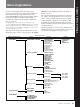
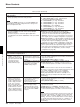
OPERATIONAL FUNCTION [Operational]: Operation
settings
Description of settings
PREROLL TIME [> Preroll]: Set the preroll time. The preroll time can be set in one-second increments to
between 0 and 15 seconds (0 SEC [>> 0 SEC] to 15 SEC
[>> 15 SEC]). When an editing controller such as the PVE-
500 has been connected, this setting is disabled and the
editing controller’s setting is in effect. Operations such as the
preroll time setting and the time data switching operation are
also performed on the editing controller.
Factory default setting: 5 SEC [>> 5 SEC]
AFTER CUE-UP [> After CUE]: Select the operating mode
following cue-up.
STOP [>> STOP]: Stop mode
∗STILL [>> STILL]: Output still pictures in search mode.
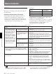
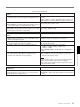
PLAY START [> PLAY Start]: Set the timing for switching
from stop mode to playback mode.
In an editing system including an editing controller such as
the PVE-500, adjusting this setting so that the delay before
switching to playback mode is the same on all the decks of
the editing system means that there is no longer a need to
synchronize the decks for editing, and the preroll time can
be shortened.
16 FRAME DELAY [>> 16 delay] to 4 FRAME DELAY
[>> 4 delay]: The larger the numerical value, the longer the
delay. By adjusting this setting, it is possible to reduce the
phase synchronization time and preroll time during editing.
Factory default setting: 5 FRAME DELAY [>> 5 delay] (for
DSR-85) or 4 FRAME DELAY [>> 4 delay] (for DSR-85P)
A1 EDIT CH [> A1 Edit CH]: Determine which audio channel
the EDIT PRESET command set on an editing controller
(such as the PVE-500) for A1 is assigned to.
∗CH-1 [>> CH-1]: Assign to channel 1.
CH-2 [>> CH-2]: Assign to channel 2.
CH-3 [>> CH-3]: Assign to channel 3.
CH-1 & CH-2 [>> CH-1&2]: Assign to channel 1 and channel
2.
A2 EDIT CH [> A2 Edit CH]: Determine which audio channel
the EDIT PRESET command set on an editing controller
(such as the PVE-500) for A2 is assigned to.
∗CH-2 [>> CH-2]: Assign to channel 2.
CH-3 [>> CH-3]: Assign to channel 3.
CH-4 [>> CH-4]: Assign to channel 4.
CH-3 & CH-4 [>> CH-3&4]: Assign to channel 3 and channel
4.
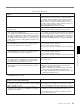
A MODE CHANGE [> Aud change]: Determine whether or
not to permit an insert editing that uses a different audio
recording mode (2- or 4-channel mode) from that which
was used for the tape loaded in the recorder.
∗OFF [>> OFF]: Do not permit.
ON [>> ON]: Permit.
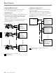
QSDI AUDIO MON [> QSDI A mon]: Determine what type of
audio signal to be output as EE audio when the selected
input is QSDI.
∗QSDI [>> QSDI]: Output the input QSDI audio as it is.
ANALOG [>> Analog]: Automatically switch audio input
selection and output analog audio.
AES/EBU [>> AES/EBU]: Automatically switch audio input
selection and output AES/EBU format digital audio.
SDI [>> SDI]: Automatically switch audio input selection and
output SDI format digital audio.
a)
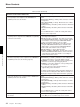
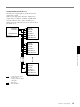
DISPLAY CONTROL [Display]: Settings related to
indications on the monitor and the unit
Description of settings
CHARA. DISPLAY [> Chara disp]: Determine whether or not
to output text (such as time code numbers) from the VIDEO
OUT 2 (SUPER) connector.
∗ON [>> ON]: Output text.
OFF [>> OFF]: Do not output text. (In spite of this setting,
pressing the MENU button causes menu text to be output.)
CHARA. POSITION [> Chara pos]: Set the position of text
superimposed on output from the VIDEO OUT 2 (SUPER)
connector to the monitor.
Use ¿ ÷ ˘ ≥ buttons on the menu control panel to adjust
the indication position while watching the monitor screen.
Press the MENU button to confirm the setting and return to
the level 1 of the setup menu.
a) Displayed only when the optional DSBK-120/120P SDI
Input/Output Board is installed.
(Continued)