
VCR Operating Instructions DSR-85, 85P


Chapter 5 Connections and Settings 57
Chapter 5 Connections and Settings
Chapter 5 Connections and Settings
This unit can be connected to an ES-7 EditStation to
configure a digital non-linear editing system.
If you use the QSDI interface, you can transfer video,
audio, time code, and other compressed data at quad
speed (four times the normal transfer rate) between
this unit and the ES-7.
The unit supports ClipLink functions, enabling index
pictures recorded on tape and ClipLink log data stored
in cassette memory to be transferred to the ES-7 in an
instant.
For a general description of ClipLink functions, refer to
“ClipLink™ Guide” supplied with the unit.
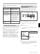
Connections for a Digital Non-Linear Editing
System
The following figure shows a connection diagram for
non-linear editing system in which this unit serves as
the recorder.
For connections of the ES-7 and its peripheral devices such
as the ESBK-7011 Control Panel, the ESBK-7045 Disk Unit,
etc., refer to your ES-7 Operating Instructions.
Note
The example connections shown in this chapter
assume that DSR-85/85P, DSR-80/80P, and DSR-60/
60P units have DSBK-100/110/120/130 (or DSBK-
100P/110P/120P/130P) option boards installed.
Settings on the DSR-85/85P
For details of video/audio input and audio mode settings,
see “Settings for Recording” (page 19).
Switch Setting
REMOTE/LOCAL REMOTE
REF. VIDEO IN 75 Ω termination ON
ES-7 EditStation
Audio input
Composite video input
Video monitor
1 75 Ω coaxial cable (not supplied)
2 9-pin remote control cable (one cable
is supplied with the DSR-85/85P)
3 Cable with RCA phono plugs
(not supplied)
DSR-85/85P
(recorder)
REF. VIDEO IN
QSDI OUTPUT
QSDI
INPUT
MONITOR
AUDIO
VIDEO OUT 2
(SUPER)
B B OUT(1/2/3/4)
QSDI OUTPUT
QSDI INPUT
REMOTE RECORDER
1
1
1
2
13