
VCR Operating Instructions DSR-85, 85P


58 Chapter 5 Connections and Settings
Chapter 5 Connections and Settings
Connections for a Cut Editing System
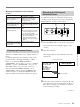
The following figure shows a cut editing system
configuration that includes two DSR-85/85Ps to serve
as the player and recorder.
Connections for a Cut Editing System
For details of connecting devices other than the DSR-85/
85Ps, refer to the instruction manual for each device.
When you select assemble or insert editing
mode on the editing controller, the EDIT
MODE indicator lights on the front panel of the
recorder and the recorder automatically enters
the selected editing mode.
DSR-85/85P
(player)
Audio input
Source monitor
Editing control unit (such as RM-
450/450CE, PVE-500, etc.)
a)
DSR-85/85P
(recorder)
REF.
VIDEO
OUT
Composite
video input
Audio input
Composite
video input
Main monitor
1 75 Ω coaxial cable (not supplied)
3 Cable with RCA phono plugs
(not supplied)
2 9-pin remote control cable (one cable
is supplied with the DSR-85/85P)
Settings on the DSR-85/85Ps (recorder and player)
For details of the video/audio input and audio mode settings
for the recorder, see “Settings for Recording” (page 19).
Note
Jog audio monitoring is not possible with the recorder
and its monitor. For this purpose use the player and its
monitor.
About reference video signals
In order to provide stable video and audio signals for
analog editing, it is necessary for the built-in time base
corrector (TBC) to operate correctly. To ensure this,
input a reference video signal synchronized with the
video signal to the REF. VIDEO IN connector and set
the REF. VIDEO IN 75Ω termination switch to ON.
QSDI OUTPUT
MONITOR
AUDIO
VIDEO
OUT 2
(SUPER)
REMOTE
QSDI
INPUT
MONITOR
AUDIO
VIDEO
OUT 2
(SUPER)
REMOTE
REF.
VIDEO IN
PLAYER
RECORDER
1
31 2 1 31 2
Switch
Recorder
Player
REMOTE
REMOTE
REMOTE/LOCAL
a) For the settings on the editing control unit,
see “Settings on an editing control unit”
(page 63).