5-011-250-12(1) Color Video Camera Operating Instructions Software Version 2.00 Before operating the unit, please read this manual thoroughly and retain it for future reference.
Table of Contents Operations Using the Supplied Infrared Remote Commander Before Starting Operations ....................... 26 Turning on the Power ................................ 26 Operating Multiple Cameras Using the Infrared Remote Commander ................... 26 Pan/Tilt Operation ......................................27 Zoom Operation ........................................ 28 Adjusting the Camera ............................... 28 Focusing on a subject ...........................
PICTURE/OPTICAL FILTER Menu ................. 41 PICTURE ................................................. 41 OPTICAL FILTER ......................................42 PAN TILT/PRESET RECALL Menu .................43 PAN TILT .................................................43 PRESET RECALL ..................................... 44 PICTURE PROFILE Menu (BRC-X400/X401) .................................................................. 44 VIDEO OUT Menu ...................................... 45 HDMI .............
Setting the PTZF Control ― PTZF control Menu ................................ 88 PTZF control tab ................................... 88 Preset position tab ............................... 89 PTZ TRACE (BRC-X400/X401) ............... 90 Setting the Streaming — Streaming Menu .....................................92 Streaming tab ........................................92 Using NDI|HX .............................................93 Appendix Message List .............................................
This manual or the software described herein, in whole or in part, may not be reproduced, translated or reduced to any machine readable form without prior written approval from Sony Corporation.
Precautions for Preventing Access to the Camera by an Unintended Third Party Features Pan/Tilt/Zoom CMOS video camera equipped with a small built-in pan-tilt head The camera settings may be changed by an unintended third party on the network, depending on the usage environment.
Preset function Extensibility Up to 100 preset data can be stored in the VISCA command and up to 256 preset data in the CGI command. On the PTZ Motion Sync function*3, pan, tilt, and zoom work together to enable smooth preset operations. 4K Option (SRGL-4K) SRG-X400/X402/201M2/X120/HD1M2 (HD model) supports 4K video output via HDMI and 4K IP streaming by installing the optional 4K Option license. (page 69)*3 NDI|HX This camera is compatible with NDI|HX of NewTek, Inc.
and PoE+ power supply device with a LAN cable. The green lamp stops flashing and lights up when start-up is complete. The green lamp flashes when the camera receives an operation command from the supplied remote commander. The lamp lights up in orange when the POWER button on the supplied remote commander is pressed and the camera enters in the standby mode. The yellow lamp flashes while upgrading the firmware.
VISCA RS-422 OUT terminal When you connect multiple cameras, connect it to the VISCA RS-422 IN terminal of the next camera in the daisy chain connection. Switch No. IR SELECT switch Select the camera number when you operate multiple cameras with the same remote commander.
Baud Rate settings of VISCA RS-422 communication Switch state Baud Rate ON 38400 bps OFF 9600 bps 12 V (DC power input) terminal Connect the AC adapter (supplied). Note Do not use any AC adapter other than the supplied AC adapter. Otherwise, a fire or malfunction may occur. * Turn the power off and on to reflect the changes after setting. Bottom HDMI OUT terminal Supplies the images as an HDMI video signal.
• Objects behind glass • Objects with horizontal stripes • Objects on which bright lights are cast or reflected • Nightscapes and other dark objects with blinking lights • Lit objects shot with darkened exposure adjustment or exposure compensation settings Infrared Remote Commander (supplied) DATA SCREEN button Press this button to display the main menu PAGE. Press it again to close the menu. If you press the button when a lower-level menu is selected, the display goes back to a higherlevel menu.
Required batteries Note Two R6 (size AA) batteries are required for the remote commander. To avoid the risk of explosion, use R6 (size AA) manganese or alkaline batteries. The BACK LIGHT button is enabled when MODE (Exposure mode) on the EXPOSURE menu is set to [FULL AUTO] (Full auto), [SHUTTER Pri] (Shutter priority), or [IRIS Pri] (Iris priority). Note Danger of explosion if the batteries are incorrectly replaced. Replace only with the same or equivalent type recommended by the manufacturer.
System Configuration This camera can be arranged into various system configurations with other products (not supplied). This section describes typical system examples, with the required components and the main usage of each system. Operating a Single Camera Using the Supplied Remote Commander What you can do with this system Operate the camera readily from a short distance.
Operating a Single Camera Using the Optional Remote Controller What you can do with this system Perform pan/tilt and zoom operations using the joystick of the remote controller.
Operating Multiple Cameras Using the Optional Remote Controller What you can do with this system • For the RS-422 connection, you can remotely operate up to seven cameras with a single remote controller. • Perform pan/tilt and zoom operations using the joystick.
Installation and Connection CAUTION Installation of the camera using the tripod screws and screw holes should not be done for installation on a ceiling or a shelf, etc., in a high position. Installing the Camera Installing the camera on a desk Installing the Camera Using the M3 Fixing Screw Holes Place the camera on a flat surface.
2 Before installing the camera Determine the shooting direction of the camera, and then make the holes for the ceiling bracket (B) and the connecting cables on the ceiling. Notes • The connecting cables cannot be passed through ceiling bracket (B). A hole for the wiring is required in the ceiling at the back of the camera where it is attached to the ceiling. • The recommended tightening torque for each screw are described in below. M3: 0.6 N·m (6.1 kgf·cm) M2.6: 0.4 N·m (4.
5 While pushing up the entire camera, attach it to the ceiling bracket (B) using the 3 screws (M3 × 8) supplied. Ceiling Ceiling Attach the wire rope. M 3×8 (supplied) Ceiling bracket (A) M3×8 (supplied) Lightly tighten screws temporarily in the order indicated in the figure. Afterwards, screw each of them firmly. 6-1 Connect the cables to the terminals at the back of the camera. Lightly tighten screws temporarily in the order indicated in the figure.
HDMI cable fixing plate Connecting the Camera M 2.6 × 6 (supplied) Connecting to an AC power supply Connect the camera to an AC outlet using the supplied AC adapter and power cord. Banding band Note Do not attach the HDMI cable on the camera, if you do not use it. 7 Adjust the image flip function to optimize the ceiling mounting status. To power supply AC adapter (supplied) Note All preset settings will return to their default settings when changing the setting of the image flip function.
2 Fix the cord of an AC adapter with the cord clamper so that it does not come out. Unlock the cord clamper and put the cord through it. AC adapter cord clamper Unlock the cord clamper lock. Cord clamper lock Network cable (commercially available) Hub with PoE+ power supply feature AC adapter cord Put the AC adapter cord through the cord clamper and lock the cord clamper. Note Notes Do not use any AC adapter other than the supplied AC adapter. Otherwise, a fire or malfunction may occur.
Devices equipped with an SDI input terminal (HD output): SRG-X400/X402/201M2/X120/HD1M2 Connecting a single camera to a switcher, recorder, or monitor Devices equipped with an HDMI input terminal SDI OUT Connecting cable with BNC connector (commercially available) HDMI cable (not supplied) To SDI input terminal To HDMI input terminal Recorder or monitor equipped with SDI input terminal Video monitor Connecting a single camera to a single remote controller (not supplied) Devices equipped with an SDI in
Using the VISCA RS-422 terminal A remote controller can be connected via the VISCA RS-422 terminal. The VISCA RS-422 allows connections of up to 1.2 km in length. Network cable (commercially available) Network cable (commercially available) * Use straight network cable. Network cable (commercially available) Note When RM-IP10 is used, make a connecting cable using the camera and the RS-422 terminal board connectors supplied with the remote controller.
Connecting multiple cameras using VISCA over IP When you connect multiple cameras to a single remote controller or when you connect multiple cameras to multiple remote controllers with a computer, use a switching hub for the connection. Connecting a commercially available video switcher For 4K output (HDMI output only) When you want to switch cameras, connect a commercially available video switcher. For the connection to the video switcher, refer to the operating instructions of the switcher.
For HD output When you want to switch cameras, connect a commercially available video switcher. For the connection to the video switcher, refer to the operating instructions of the switcher.
For multiple cameras Up to 7 cameras can be connected. Connecting to commerciallyavailable microphones etc. Connect a commercially-available microphone, mixer, etc. Input audio will be transmitted to the HDMI OUT and SDI OUT output and IP network streaming in stereo format. Switch between the microphone input and line input from the Administrator menu on the web browser. Connect a commercially-available microphone when using the microphone input.
Operations Using the Supplied Infrared Remote Commander Operating Multiple Cameras Using the Infrared Remote Commander Before Starting Operations 1 Set the IR SELECT switch on the back of the camera you want to operate to 1, 2, or 3. 2 Press the CAMERA SELECT button on the remote commander that corresponds to the number set in step 1. Before operating, check that the camera and peripheral devices are properly installed and connected.
When the camera moves in a different direction from what you intended Pan/Tilt Operation The camera is preset to face toward the right whenever the button is pressed. You might wish to reverse the direction in which the camera moves, for example, when you change the direction of the camera while checking the picture on the screen. In such cases, press the 2 (REV) button while holding down the L/R DIRECTION SET button.
Zoom Operation Adjusting the Camera Press either of the ZOOM buttons. Subject appears farther away. (Wide angle) Zooms in or out slowly (SLOW side) Subject appears closer. (Telephoto) Zooms in or out quickly (FAST side) Note When you perform pan/tilt operations while the camera is in telephoto mode, the moving speed of the image on the screen may be a little jerky. Focusing on a subject To adjust the focus automatically Press the AUTO button.
Note Storing the Camera Settings in Memory– Preset Feature Before you store the position, zoom, focus, etc. of the camera, make sure to install and secure the camera in place to use it properly. Settings, including the camera position, zoom, focus, and backlighting, can be stored in a preset. You can also store presets from the Administrator menu on a web browser. For details, see “Preset position tab” (page 89).
Recording pan/tilt and zoom operations Storing Camera Pan/Tilt and Zoom Operations 3 LE C T PO W ER – PTZ TRACE function (BRC-X400/X401) 2, 4 SE M AN UA L A 2 AM ER R LIG POSITION 1~6 6 ET SIT P RE AN SE -TIL T T ET PO IL T -T ES T W T SE 1 Adjust the operation start position of the camera. 2 Hold down the PRESET button and press any of the POSITION1 to 6 buttons in which you want to store the settings. Recording starts.
Canceling a menu Operating Menus When the main menu is displayed, press the DATA SCREEN button once. When a setting menu is displayed, press the DATA SCREEN button twice. This section explains how to configure the camera using the supplied remote commander. For details on the menu items, refer to page 33 through page 50. Displaying a menu 1 Press the DATA SCREEN button. The main menu is displayed. 2 Use the or button to move the cursor to the menu item you want to change.
or : Indicates use of the /// buttons to select menu items and settings. These correspond to the joystick directions on a remote controller. : Indicates use of the HOME button (equivalent to ENTER) to confirm the menu item or setting selection, or to advance to the next screen or next operation. This corresponds to the joystick button on a remote controller. : Indicates use of the DATA SCREEN button (equivalent to MENU) to show/hide the menu screen.
Setting menu EXPOSURE Menu The setting menu selected on the main menu is displayed. The EXPOSURE menu is used to set the items regarding the exposure. You can set the menu from the Administrator menu on a web browser. For details, see “Picture tab” (page 70). Setting menu The name of the setting menu currently selected is displayed. Note Cursor The cursor selects a setting item. Press the or button of the remote commander to move the cursor up or down.
SPEED (Exposure - Shutter speed) GAIN LIMIT (Exposure - Auto gain Max. value) When [MODE] is either [MANUAL] or [SHUTTER Pri], select the electronic shutter speed. When the signal format is 59.94 or 29.97 You can choose from [1/1], [2/3], [1/2], [1/3], [1/4], [1/6], [1/8], [1/10], [1/15], [1/20], [1/30], [1/50], [1/60], [1/90], [1/100], [1/125], [1/180], [1/250], [1/350], [1/500], [1/725], [1/1000], [1/1500], [1/2000], [1/3000], [1/4000], [1/6000], [1/10000].
When the signal format is 23.98 You can choose from [1/24], [1/25], [1/40], [1/48], [1/50], [1/60], [1/96], [1/100], [1/120], [1/144], [1/192], [1/200], [1/288], [1/400], [1/576], [1/1200], [1/2400], [1/4800], [1/10000]. COLOR Menu The COLOR menu is used to adjust the white balance and the color. You can set the menu from the Administrator menu on a web browser. For details, see “Picture tab” (page 70).
SPEED (White balance - Speed) R-G, R-B, G-R, G-B, B-R, B-G (Color matrix - R-G, R-B, G-R, G-B, B-R, B-G) (BRC-X400/X401) Adjust the speed at which the camera reaches the white convergence point when [AUTO1] or [AUTO2] is chosen. Choose a value from [1], [2], [3], [4], and [5]. [5] is the fastest and [1] is the slowest. You can set a coefficient for each combination of RGB individually, to adjust the hue of the entire picture. Choose a value from [–99] to [0] to [+99].
correction elements become greater compared to the vertical elements. DETAIL Menu BW BALANCE (Detail - BW balance) The DETAIL menu is used to adjust the image enhancer function. You can set the menu from the Administrator menu on a web browser. For details, see “Picture tab” (page 70). You can adjust the balance between contours in black on the low brightness side of the spectrum and contours in white on the high brightness side. Choose from [TYPE0] to [TYPE4].
KNEE Menu (BRC-X400/X401) GAMMA/VISIBILITY ENHANCER Menu (BRC-X400/ X401) The KNEE menu is used to adjust the KNEE. You can set the menu from the Administrator menu on a web browser. For details, see “Picture tab” (page 70). The GAMMA/VISIBILITY ENHANCER menu is used to adjust GAMMA correction and VISIBILITY ENHANCER function. You can set the menu from the Administrator menu on a web browser. For details, see “Picture tab” (page 70).
less contrast in darker regions and more contrast in lighter regions. [ITU709]: Gamma curve equivalent to ITU-709. VISIBILITY ENHANCER Menu (SRG-X400/X402/201M2/ X120/HD1M2) PATTERN (Gamma - Pattern) Choose a value from [0] to [51]. This can be chosen when [SELECT] is set to [PATTERN]. You can set the menu from the Administrator menu on a web browser. For details, see “Picture tab” (page 70). PATTERN FINE Choose a value from [0] to [9]. When [PATTERN] is [0], [0] cannot be chosen for [PATTERN FINE].
• Lit objects shot with darkened exposure adjustment or exposure compensation settings ZOOM/FOCUS Menu (BRCX400/X401, SRG-X400/X402/ 201M2) The ZOOM/FOCUS menu is used to select the zoom/focus mode. You can set the menu from the Administrator menu on a web browser. For details, see “PTZF control tab” (page 88). ZOOM MODE (Zoom - Zoom mode) Select the zoom mode. [OPTICAL]: Zooms objects within the optical zoom range (up to 20x) of the camera.
FOCUS Menu (SRG-X120/ HD1M2) PICTURE/OPTICAL FILTER Menu The FOCUS menu is used to select the focus mode. You can set the menu from the Administrator menu on a web browser. For details, see “PTZF control tab” (page 88). The PICTURE/OPTICAL FILTER menu is used to adjust picture quality improvement features and optical filters. You can set the menu from the Administrator menu on a web browser. For details, see “Picture tab” (page 70). MODE (Focus - Focus mode) Select the focus mode.
FLICKER CANCEL (Picture - Flicker cancel) Note When this is turned [ON], the flicker correction feature becomes enabled. When this is turned [OFF], the flicker correction feature becomes disabled. When this setting is set to [AUTO], set [EXPOSURE MODE] to [FULL AUTO]. ICR THRESHOLD (Day/Night ICR – Switching level) Note Depending on conditions such as the type of illumination and shutter speed, the flicker correction feature may not be effective.
Setting range of LEFT/RIGHT PAN TILT/PRESET RECALL Menu CENTER (±0°) The PAN TILT/PRESET RECALL menu is used to select the pan/tilt/preset recall mode. You can set the menu from the Administrator menu on a web browser. For details, see “PTZF control tab” (page 88). –170° +170° Setting range of DOWN/UP PAN TILT +90° PAN LIMIT (Pan-Tilt - Pan limit) Set whether to limit the pan rotation range. [OFF]: Do not apply range limit. [ON]: Apply range limit.
PAN TILT SLOW (Pan-Tilt - Slow Pan-Tilt mode) PICTURE PROFILE Menu (BRCX400/X401) You can select slow speed panning/tilting. [OFF]: The camera pans/tilts at the standard speed. [ON]: The camera pans/tilt speed is slower. PRESET RECALL You can select preset recall settings. RECALL SPEED (Preset - Speed select) You can select preset recall speed. [COMPATIBLE]: Work differently depending on the commands for preset recall. • For VISCA command: Pan/tilt work with the speed set by each preset.
• COLOR MATRIX SELECT LEVEL PHASE R-G R-B G-R G-B B-R B-G • DETAIL LEVEL MODE Settings can be adjusted individually after recalling a picture profile. To save settings, save to a preset. VIDEO OUT Menu You can set [COLOR SPACE] from the Administrator menu on a web browser. For details, see “Installation tab” (page 67). HDMI COLOR SPACE (Video out - Color space) Set the color space of HDMI output. Notes H PHASE (BRC-X400/X401) • The settings for a picture profile cannot be changed.
Note SYSTEM Menu When [TALLY LEVEL] is set to [OFF], the tally lamp does not light up. You can set the menu from the Administrator menu on a web browser. For details, see “Installation tab” (page 67) or “PTZF control tab” (page 88). TELE CONVERT MODE (System - Tele convert) (BRC-X400/X401, SRG-X402) You can shoot using 2× magnification. [OFF]: Does not use the magnification function. [2x]: Uses the magnification function.
[NEUTRAL]: The pan position is not moved automatically. [SIDE]: The pan position is moved to the end automatically. PTZ TRACE Menu (BRC-X400/ X401) Notes • When the mode is set to [SIDE], the pan position is moved to the end, exceeding the limit even if [PAN LIMIT] is specified. • After the camera is turned on from the standby mode, the camera position moves to the position recorded on PRESET1.
During playback, the menu screen display continues, with *PLAYING* displayed at the bottom of the screen. Recording pan/tilt and zoom operations 1 2 3 4 Note Select the trace number you want to record in TRACE NO. Playback stops if a pan, tilt, or zoom operation is performed during playback using the remote commander or a remote controller. Move the cursor to RECORD, and press the HOME button. *SETTING (ENTER TO START REC)* is displayed at the bottom of the screen.
PAGE6: Items in the PICTURE/OPT.FILTER menu PAGE7: Items in the PAN TILT/PRESET menu PAGE8: Items in the VIDEO OUT menu PAGE9: Items in the SYSTEM menu PAGE10: Device information of the camera and status of switch settings on the back of the camera PAGE11: Network settings STATUS Menu The [DEVICE INFO] and [NETWORK] screens are only in the STATUS menu.
4K OPTION (Option - 4K Option) (SRGX400/X402/201M2/SRG-X120/HD1M2) Displays installation status of 4K option. NETWORK The NETWORK menu is used to configure Network settings. MAC ADDRESS (Status - MAC address) Displays the MAC address of the camera. IP ADDRESS (Status - IP address) Displays the IP address set up on the camera. SUBNET MASK (Status - Subnet mask) Displays the subnet mask currently set up for the camera.
Menu Configuration The camera menu is configured as described below. For more details, refer to the pages in parentheses. The initial settings of each item are in bold. Only supported functions are displayed.
(page 35) 52
(page 35) (page 37) (page 38) (page 38) (page 39) 53
(page 40) (page 41) (page 41) (page 43) (page 44) (page 45) 54
(page 45) (page 46) (page 46) (page 46) (page 47) 55
(page 49) * When 4K Option is installed 56
Accessing the Camera from a Web Browser Setting-up the Computer System configurations required for the Computer are shown in the following (as of March 2020). You can access the camera from a web browser on a computer to upgrade the firmware and to change settings. An IP address must be set on the camera for access from a web browser. For details on IP address settings, refer to “RM-IP Setup Tool Guide.” OS/Web browser Windows OS version Windows 8.
Accessing the Camera from a Web Browser Changing the Initial Password Start a web browser on the computer and enter the IP address of the camera in the address bar. Accessing the camera from a web browser for the first time requires to change the administrator password. The default administrator name and password are as follows. Administrator name: admin Password: Admin_1234 Authentication by user ID and password is required to access the camera.
Displaying the Viewer Screen Properly When You Use Antivirus Software on Your Computer To operate the viewer screen correctly, set the security level of Internet Explorer to [Medium] or lower as follows. • When you use antivirus software, security software, personal firewall, or pop-up blocker on your computer, the camera performance may be reduced, for example, the frame rate for displaying the image may be lower. • Web pages displayed when you access the camera are JavaScript.
When the SSL Function is Used When Internet Explorer is used When you enter the camera IP address, “Certificate Error” may appear according to the status of the certificate set on the camera. In this case, click [Continue to this website (not recommended)] to continue. The live viewer window appears (in the SSL communication). When [Enable (Allow HTTP connection for some clients)] (page 83) is selected To access the HTTP or SSL connection, enter the following in the address box of the web browser.
Operating the Camera from a Web Browser Operating the Camera This section explains the names and functions of the parts of the live viewer. For details, see the specified pages. This section explains how to monitor the image from the camera using a web browser. Live viewer Camera settings should be set by administrator. For details on the camera settings, see “Configuring the Camera from a Web Browser” (page 64).
Standby / Select [×1] to display the image size selected in [Size] (page 75) of the Video menu. Select [Full] to display images according to the display size. Select [Fit] to display images with fixed aspect ratio according to the display size. On Click to turn on the camera or put it in the standby mode. is displayed when the camera is on standby. Clicking changes the display to , starts flashing, and then stops flashing when the camera turns on.
Camera panel Preset position panel For BRC-X400/X401, the panel is displayed when [Mode1] or [Mode2] is selected for the preset mode on the PTZF operation tab. By using the control panel, you can operate the pan/tilt, moving to the home position, zoom, and focus of the camera for the monitor image currently displayed. Preset control This is displayed only when preset positions for the camera are stored in memory. Stored preset positions are displayed.
Configuring the Camera from a Web Browser Basic Operations of the Administrator Menu This section explains how to set the functions of the camera by an administrator. You can set all functions of the camera in the Administrator menu according to the user’s usage. Click [Setting] on the viewer screen to display the Administrator menu. For details on monitoring of the camera image, see “Operating the Camera from a Web Browser” (page 61).
OK Configuration of the Administrator Menu Click to enable the settings in each tab. The settings are not applied to the camera until you click this button. Cancel System menu Click to nullify the settings and return to the previous settings. Displays the System menu (“Configuring the System ― System Menu” (page 66)). Reload Click to cancel the operation changed on a web browser and update the display on a web browser after obtaining the information from the camera.
PC clock Displays the date and time set on your computer. Configuring the System ― System Menu When you click in the Administrator menu, the System menu appears. Use this menu to set the basic settings of the camera. The System menu consists of the [Information], [Date & time], [Installation], [Initialize], [System log], and [Access log] tabs. Date & time format Select the date and time format to be displayed on the viewer from the drop-down list.
Note Notes • This is enabled only when the SYSTEM SELECT switch or format setting of video output is set to 1920×1080. • Selecting the checkbox of [Tele convert] narrows the angle of view. If the time zone selected in [Time zone] is different from that set on the computer, the date and time applied the time zone difference to are set on the camera. Installation tab Menu overlay (SDI) Clearing the checkbox does not display the OSD menu or message on the SDI output screen.
Video out Initialize tab Format (DEVICE INFO - SYSTEM MODE) Select the video output format of the signal to be output from the HDMI OUT and SDI OUT terminals. You can change the video format from this menu when the SYSTEM SELECT switch is set to 6. When the SYSTEM SELECT switch is set to a value other than 6, the setting status of the SYSTEM SELECT switch and the format level of the CAMERA SETUP switch are displayed. Video output format 59.94 Hz system 3840×2160/29.97p Initialize 1920×1080/59.
Import setting file Used when you import the stored setting data of the camera. Click [Choose File] to select the setting file. The camera is configured according to the setting data. Access log tab Access log Displays the access history of the camera. Click [Reload] to reload the latest data. Notes • The following items cannot be exported or imported in [Export setting file] or [Import setting file]. – Network settings – QoS settings – User settings – Access limit settings – 802.
To Enable the Optional Function by Purchasing a License You can use optional functions by purchasing a license and installing the license file. Before performing this operation, purchase a license in advance and obtain the purchase code. Setting the Camera Image ― Video Menu Picture tab Note For details on how to purchase a license, contact a distributor. Perform operations of steps 1 and 3 on the Administrator menu of the camera.
• The other setting items registered to Preset 1 in advance are not changed. See “Preset Items and Image Setting File Items” (page 96) for the other setting items. Gain point (EXPOSURE - GAIN POINT) When you set [Slowest] (lower limit of the shutter speed) to be lower than the output image frame rate, the shutter speed controls exposure based on the [Gain point] setting. Normally, when exposure is adjusted with sensitivity, noise is prominent when sensitivity is increased to brighten the image.
Speed (COLOR - SPEED) When [Mode] is set to [Auto1] or [Auto2], you can adjust the speed at which the camera reaches the white convergence point. Select a value from [1], [2], [3], [4], or [5]. [5] is the fastest and [1] is the slowest. Exposure compensation (EXPOSURE - EX-COMP, LEVEL) Select the exposure correction value from the dropdown list to adjust the target brightness for the automatic exposure setting. Selecting higher value brightens the image and lower value darkens the image.
Detail Highlight detail (DETAIL - HIGHLIGHT DETAIL) You can adjust the contour level added to brightly-lit objects. Select a value from [0] to [4]. The higher the value, the greater the contour emphasis. Set when you want to emphasize the contour of a brightly-lit object in a bright background. Select the sharpness. Mode (DETAIL - MODE) When you select [Auto], contour correction signal is automatically added. When you make adjustment manually, select [Manual].
Black gamma range (GAMMA - BLACK GAMMA RANGE) You can adjust the brightness range that black gamma works. Select from [Low], [Middle], and [High]. The brightness range becomes narrow when you select [Low], and it becomes large when you select [High]. [Advanced]: Set the noise reduction strength of 2D/ 3D individually and removes noise simultaneously. NR (XDNR) This setting is available when [NR mode] is set to [Simple]. Select from Off (minimum) or level [1] through level [5] (maximum) for noise reduction.
Frame rate Set the frame rate of the image. “fps” is a unit indicating the number of frames transmitted per second. Selectable frame rate is changed depending on the video output format which is selected by the SYSTEM SELECT switch on the back of the camera or format setting of video output. Video codec tab I-picture mode Select from [Time] or [Frame] to specify the insertion interval of H.264/H.265 I-picture. [Time]: Set I-picture insertion interval by time.
Custom string The superimposed content for each position is described. is displayed for Date & time, for Zoom ratio, and for Camera name. You can add an arbitrary string around them. Superimpose tab Text color Select the font color of the superimposed text. Background color Select the background color of the superimposed text. Select whether to superimpose the custom string on the image. Three strings and one logo (still image) can be superimposed simultaneously.
Note When [Auto] is selected, set the exposure mode to [Full auto]. Setting the Audio — Audio Menu Threshold (OPTICAL FILTER - ICR THRESHOLD) When Day/Night ICR mode is set to [Auto], choose a level to switch from Night mode to Day mode in the range from 0 to 255. The mode is subject to change from Night mode to Day mode the smaller the chosen value is. When you click in the Administrator menu, the Audio menu appears. Use this menu to set the audio functions of the camera.
[AAC (128kbps)]: Select this type when you prioritize the data capacity. This setting will not effect on the audio signal superimposed on HDMI/SDI. Configuring the Network — Network Menu When you click in the Administrator menu, the Network menu appears. Use this menu to configure the network to connect the camera and the computer. The Network menu consists of the [Network] tab. Network tab This section provides the menus for connecting the camera through the network cable.
Default gateway Enter the default gateway. Secondary DNS server Displays the current secondary DNS server. IPv6 address 1 IPv6 address 2 Displays the current IPv6 address. Common setting Configure the common setting for IPv4 and IPv6 network. IPv6 default gateway Displays the current IPv6 default gateway. HTTP port number Enter the HTTP port number. Normally select 80. LinkLocal IPv6 address Displays the current link-local IP address.
IPv4 QoS Move up Increases the priority of the rule. Select a rule from the QoS table to prioritize and click [Move up]. Enable Select the checkbox to configure the QoS setting for IPv4. Move down Decreases the priority of the rule. Select a rule from the QoS table to lower its priority and click [Move down]. Rule Used to register, edit and delete QoS. No. Select the number to use when registering on the QoS table. When you select a registered number, the registered QoS information is displayed.
User tab Setting the Security — Security Menu When you click in the Administrator menu, the Security menu appears. The Security menu consists of the [User], [Access limit], [SSL], [802.1X], [Referer check] and [Brute force attack protection] tabs. Administrator and User Set the user names and passwords of Administrator and up to 9 types of user (User 1 to User 9), and the viewer mode of each user. Enter your password in [Current password] when changing the user name and password or deleting the user.
Access limit Re-type password To confirm the password, retype the password that you entered in the [Password] box. Set an access limit to the camera. Enable Select the checkbox to enable the access limit. Viewer mode You can select the viewer mode to be displayed after authentication when the viewer is displayed. Rule [Administrator]: The user can operate all functions including the setting menu in this mode. [Full]: The user can operate all functions other than the setting menu and power.
Note Notes SSL connection will load the camera down; therefore, not all images may be downloaded, and the mark may appear when the camera accesses from the web browser. In this case, reload the window. Press the F5 key on the keyboard to reload. • When using the SSL function, always configure the settings after setting the date and time of the camera. If the date and time are not correctly set, it may cause web browser connection problems. • Reload the window when you change the SSL setting.
To delete the imported certificate or self-signed certificate Click [Delete] to delete the certificate or self-signed certificate imported to the camera. Note The import process becomes invalid if the selected file is not a certificate or the imported certificate is not allowed. Private key password Enter the password for the private key information included in the certificate using up to 50 characters. This text box is active only when [Certificate options] is set to [Use an external certificate].
• When using the 802.1X authentication function, always configure the settings after setting the date and time of the camera. If the date and time are incorrect, port authentication may not be performed correctly. 802.1X System configuration of the 802.1X network Setting Enable Select the checkbox to enable the 802.1X authentication function. EAP identify Enter the user name to identify the client in the 802.1X authentication server up to 250 characters.
Trusted CA certificate To display client certificate information When the client certificate has been set in the camera correctly, its information appears on [Status], [Issuer DN], [Subject DN], [Available period] and [Extended key usage]. You can import a trusted CA certificate (server certificate or route certificate) to the camera. Up to 4 certificates from trusted CAs can be imported. Only the PEM format is supported. Status Shows if the status of the client certificate is valid or invalid.
Attacker list Confirm the IP address of the user detected as an attacker. Host name Enter the host name or IP address of the computer that supplies the web page you want to register on the Exception list. Port number Enter the port number of the computer that supplies the web page you want to register on the Exception list. Set Register the values of the [Host name] and [Port number] you entered to the list of the selected number. Delete Delete the contents of the list selected with [No.].
[Digital]: An image can be zoomed up to 20× optical zoom and 12× digital zoom (including Clear Image Zoom) with up to a total of 240× zoom. Setting the PTZF Control ― PTZF control Menu Focus When you click in the Administrator menu, the PTZF control menu appears. The PTZF control menu consists of the [PTZF control] and [Preset position] tab. This is the setting related to the focus. Focus mode (FOCUS - MODE) Select the focus mode. [Auto]: The focus is automatically adjusted.
Ramp curve (PAN TILT - RAMP CURVE) Set the acceleration/deceleration curve for pan/tilt. [Step]: Each time you click the mouse, the camera moves (pans, tilts or zooms) according to the set level. If you keep the mouse held down for 1 second or more, the operation mode is temporarily changed to [Normal]. When you release the mouse, camera operation stops and the [Step] mode is restored. When you select [Step], [Pan-Tilt level] and [Zoom level] are available. Note It is fixed to [Mode 1] on this camera.
Speed Pan/tilt speed when recalling the selected preset. This is available when [Speed select] is set to [Separate]. • For BRC-X400/X401, when [Trace] is selected for [Preset mode] on the PTZF control tab, you cannot perform any operations on the Preset position tab. Select [Mode 1] or [Mode 2] for [Preset mode] on the PTZF control tab to perform operations. PTZ TRACE (BRC-X400/X401) Preset mode (BRC-X400/X401) Display the current preset mode.
Record PTZ trace list PTZ trace number Start Start recording on the selected PTZ trace number. Perform pan/tilt/zoom operations to record. Recording stops when the recording time reaches its maximum time. Stop Stop PTZ trace recording. Operation Thumbnail PTZ trace name Display the PTZ trace number, PTZ trace name, and thumbnail. “Empty” is displayed for the thumbnail of the unrecorded PTZ trace. Select the PTZ trace you want to play back.
number will be used for every transmission, based on the port number specified here. Setting the Streaming — Streaming Menu Multicast streaming Set whether the camera uses multicast streaming with video data and audio data or not. It reduces the transmission load on the camera by having a computer of the same segment network receive the same transmitting data. When you click in the Administrator menu, the Streaming menu appears. Use this menu to set the items for the transmission by unicast or multicast.
RTSP time out Specify the time for the time out by the Keep-Alive command from RTSP streaming. You can set the time out from [0] second to [600] seconds. At the [0] setting, time out of the Keep-Alive command is not available. Using NDI|HX To use NDI|HX, you are required to purchase the license key. Purchasing the license key You can purchase the license key from the following URL of NewTek, Inc. http://new.
Appendix Message List The following messages and indications may appear on this camera. Perform the following as necessary. Camera Lamp Display Lamp status Description and solution POWER lamp (orange) and NETWORK lamp (green) are flashing. An error has occurred in the camera. Details of the error are displayed in the main menu. Check the details of the error before solving the problem.
Troubleshooting Before sending your camera for service, check the following to troubleshoot the problem. If the problem still persists, consult the Sony Service Center. Symptom Cause The power of the camera is not turned on. The AC adapter is not firmly connected to Firmly insert the AC adapter all the way. the DC IN 12 V terminal. The camera does not work, even when buttons on the remote commander are pressed. Remedy The power cord is not firmly connected to the AC adapter or the power supply.
Symptom Cause Remedy Problems are not resolved although measures were taken. ― Remove the plug of the power cord from the AC outlet, then reinsert it into the AC outlet after waiting a while. Preset Items and Image Setting File Items Items stored in the preset and image setting file are shown in the following lists. Item stored in the preset : Stores settings by preset. : Applies the settings to the camera at the next start-up when they are stored in Preset 1.
Camera Settings Item name on the OSD menu Item name on the Administrator menu Items other than the OSD/Administrator menu Item stored in the preset Item stored in the image setting file EXPOSURE MODE Mode (Exposure) - ● ○ IRIS Iris - ● ○ GAIN Gain - ● ○ GAIN LIMIT Auto gain Max.
Item name on the OSD menu GAMMA LEVEL Item name on the Administrator menu Level (Gamma) Items other than the OSD/Administrator menu Item stored in the preset Item stored in the image setting file - ● *1 ○ *1 *1 ○ *1 BLACK GAMMA Black gamma level - ● BLACK GAMMA RANGE Black gamma range - ● *1 ○ *1 *1 ○ *1 BLACK LEVEL Black level - ● KNEE SETTING On/Off Knee setting (On/Off) - ● *1 ○ *1 KNEE MODE Knee mode - ● *1 ○ *1 *1 ○ *1 KNEE SLOPE Knee slope - ● KNEE POINT Knee
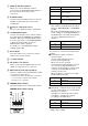
Pan/Tilt function Horizontal ±170 degrees Maximum speed: 101 degrees/ second Minimum speed: 0.5 degrees/ second Maximum speed (when the preset is recalled): 300 degrees/second Minimum speed (when the preset is recalled): 1.1 degrees/ second Vertical +90 degrees, –20 degrees Maximum speed: 91 degrees/ second Minimum speed: 0.5 degrees/ second Maximum speed (when the preset is recalled): 126 degrees/ second Minimum speed (when the preset is recalled): 1.1 degrees/ second Specifications System 3840 × 2160/29.
Operating temperature 0° C to 40° C (32° F to 104° F) Storage temperature –20°C to +60°C (–4°F to +140°F) External dimensions (Dimensions page 101) 158.4 × 177.5 × 200.2 mm (6 1/4 × 7 × 8 inches) (width/height/depth) (without protrusions) Mass Approx. 1.
Dimensions Front 170° 170° Top Bottom Side Ceiling bracket (B) Unit: mm (inches) 101
SYSTEM SELECT switch settings Notes • Be sure to set the switch before you turn on the camera. Turn on the power after you set the switch. • Be sure to use a Phillips-head screwdriver when changing the switch position. If you use a tool other than the designated screwdriver, the crossed groove may be damaged. Video output format for the HDMI OUT/SDI OUT terminal can be set with this switch.
Notes • Connect the GNDs of both devices together to stabilize the voltage level of the signal. • When preparing cables, use network cables of category 5e or more and equivalent to or higher than shielded twisted pair cables.
Sony Corporation