XR-CA600/CA600V/CA600X SERVICE MANUAL AEP Model UK Model Ver 1.0 2001.02 Photo: XR-CA600X Model Name Using Similar Mechanism XR-C5300R Tape Transport Mechanism Type MG-25G-136 SPECIFICATIONS Cassette Player section General Tape track Wow and flutter Frequency response Signal-to-noise ratio 4-track 2-channel stereo 0.
XR-CA600/CA600V/CA600X TABLE OF CONTENTS 1. GENERAL Location of Controls ....................................................... 3 Setting the Clock ............................................................. 4 2. DISASSEMBLY 2-1. 2-2. 2-3. 2-4. Disassembly Flow ........................................................... Mechanism Deck (MG-25G-136) ................................... MAIN Board ................................................................... Heat Sink (ISO2P) ....................
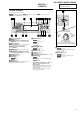
XR-CA600/CA600V/CA600X SECTION 1 GENERAL This section is extracted from instruction manual. Location of controls Refer to the pages listed for details.
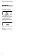
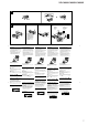
XR-CA600/CA600V/CA600X Setting the clock The clock uses a 24-hour digital indication. Example: To set the clock to 10:08 1 Press (MENU), then press either side of (DISC/PRESET) or (PRESET) repeatedly until “CLOCK” appears. 1 Press (ENTER). The hour indication flashes. 2 Press either side of (DISC/PRESET) or (PRESET) to set the hour. 3 Press the (+) side of (SEEK). The minute indication flashes. 4 Press either side of (DISC/PRESET) or (PRESET) to set the minute. 2 Press (ENTER). The clock starts.
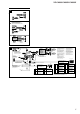
XR-CA600/CA600V/CA600X 2 A AUDIO OUT B XR-CA600X/CA600V/CA600 only Nur XR-CA600X/CA600V/CA600 XR-CA600X/CA600V/CA600 seulement Solo XR-CA600X/CA600V/CA600 Alleen voor de XR-CA600X/CA600V/CA600 BUS AUDIO IN BUS CONTROL IN AUDIO OUT BUS AUDIO IN * Source selector Signalquellenwähler Sélecteur de source Selettore di fonte Geluidsbronkiezer BUS CONTROL IN supplied * not nicht mitgeliefert non fourni non in dotazione niet bijgeleverd 3 RCA pin cord (not supplied) Cinchkabel (nicht mitgeliefert) Cordon
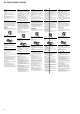
XR-CA600/CA600V/CA600X Cautions Vorsicht Précautions Attenzione Let op! • This unit is designed for negative earth 12 V DC operation only. • Do not get the wires under a screw, or caught in moving parts (e.g. seat railing). • Before making connections, turn the car ignition off to avoid short circuits. • Connect the power connecting cord (not supplied) to the unit and speakers before connecting it to the auxiliary power connector. • Run all earth wires to a common earth point.
XR-CA600/CA600V/CA600X 4 A B c 5 1 2 3 4 Dashboard Armaturenbrett Tableau de bord Cruscotto Dashboard 182 Fire wall Motorraumtrennwand Paroi ignifuge Parete tagliafiamma Brandschot 1 mm 5 Bend these claws outward for a tight fit, if necessary. 53 m m 4 Falls erforderlich, diese Klammern für einen sicheren Halt hochbiegen. 6 6 5 Piegare questi morsetti verso l’esterno per un‘installazione più sicura, se necessario. 1 2 5 6 Plier ces griffes pour assurer une prise correcte si nécessaire.
XR-CA600/CA600V/CA600X SECTION 2 DISASSEMBLY • This set can be disassembled in the order shown below. 2-1. DISASSEMBLY FLOW Note 1: The process described in can be performed in any order. Note 2: Without completing the process described in Note 3: Illustration of disassembly is omitted. , the next process can not be performed. SET FRONT PANEL SECTION (Note 3) COVER (Note 3) 2-2. MECHANISM DECK (MG-25G-136) (Page 8) 2-3. MAIN BOARD (Page 9) 2-4.
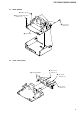
XR-CA600/CA600V/CA600X 2-3. MAIN BOARD 3 rubber cap (25) 2 three ground point screws (PTT2.6 × 6) 1 three screws (PTT2.6 × 8) 4 main board 2-4. HEAT SINK (ISO2P) 3 heat sink (ISO2P) 1 three screws (PTT2.6 × 8) 2 two screws (PTT2.6 × 12) 1 two screws (PTT2.
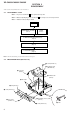
XR-CA600/CA600V/CA600X SECTION 3 ASSEMBLY OF MECHANISM DECK Note: Follow the assembly procedure in the numerical order given. 3-1. HOUSING 7 Hold the hanger by bending the claw. 5 Fit projection on C part. 2 Install the hanger onto two claws of the housing. 1 Install the catch to the hanger. hanger 4 Fit claw on B part. 3 Put the housing under A part. 6 Fit projection on D part. housing C part 8 Hold the hanger by bending the claw. D part A part B part 3-2.
XR-CA600/CA600V/CA600X 3-3. LEVER (LDG-A) / (LDG-B) shaft A shaft A shaft B shaft B shaft C 1 Fit the lever (LDG-A) on shafts A – C and install it. 3 type-E stop ring 2.0 2 Fit the lever (LDG-B) on shafts A and B and install it. 3-4. GEAR (LDG-FT) gear (LDG-D) 6 polyethylene washer hole hole 5 gear (LDG-FT) lever (LDG-A) gear (LDG-FB) 4 Align hole in the gear (LDG-D) with hole the lever (LDG-A).
XR-CA600/CA600V/CA600X 3-5. GUIDE (C) 2 guide (C) 1 three claws 3-6. MOUNTING POSITION OF CAPSTAN/REEL MOTOR (M901) two precision screws (P2 × 2) capstan/reel motor (M901) Note: Mount the motor so that the angle between of the motor and the hole for the screw becomes 30 ° as shown in this figure.
SECTION 4 MECHANICAL ADJUSTMENTS 1. Clean the following parts with a denatured-alcohol-moistened swab: playback head pinch roller rubber belt capstan idler 2. Demagnetize the playback head with a head demagnetizer. 3. Do not use a magnetized screwdriver for the adjustments. 4. The adjustments should be performed with the power supply voltage (14.4 V) unless otherwise noted. Torque Meter Meter Reading Forward CQ-102C 2.95 – 6.37 mN•m (30 – 65 g•cm) (0.42 – 0.
XR-CA600/CA600V/CA600X SECTION 6 DIAGRAMS 6-1. NOTE FOR PRINTED WIRING BOARDS AND SCHEMATIC DIAGRAMS Note on Printed Wiring Board: • X : parts extracted from the component side. • Y : parts extracted from the conductor side. • : Pattern from the side which enables seeing. (The other layers' patterns are not indicated.) Caution: Pattern face side: (Conductor Side) Parts face side: (Component Side) Parts on the pattern face side seen from the pattern face are indicated.
XR-CA600/CA600V/CA600X 6-2.
XR-CA600/CA600V/CA600X 6-3. SCHEMATIC DIAGRAM – MAIN Board (1/3) – • See page 14 for Waveform. • See page 23 for IC Block Diagrams.
XR-CA600/CA600V/CA600X 6-4. SCHEMATIC DIAGRAM – MAIN Board (2/3) – • See page 14 for Waveforms. • See page 23 for IC Block Diagrams.
XR-CA600/CA600V/CA600X 6-5. SCHEMATIC DIAGRAM – MAIN Board (3/3) – • See page 23 for IC Block Diagrams.
XR-CA600/CA600V/CA600X PRINTED WIRING BOARD – SUB Board – 6-7. SCHEMATIC DIAGRAM – SUB Board – SUB BOARD (COMPONENT SIDE) K TAPE DECK ILLUMINATION K1 S2 K2 A K LED801 A Z A1 S1 A2 K2 S2 K1 LSW801 A2 S1 (Page 22) A1 6-6.
XR-CA600/CA600V/CA600X 6-8. PRINTED WIRING BOARD – KEY Board (XR-CA600/CA600X) – 2 1 3 4 5 6 7 8 9 10 11 12 13 3 4 2 5 1 6 LED902.S907 A A MBP A B 3 2 2 4 1 6 5 K LED903, S906 EQ7 K K LED902, LED903 K A 6 4 4 2 1 PTY D DISPLAY 5 6 LIST 3 4 SOURCE 2 5 1 6 6 1 4 5 4 2 A A 2 3 1 4 3 2 LED906, 909 (LCD BACK LIGHT) 3 MENU 2 4 1 6 6 (CA600) 3 4 SOUND 2 1 5 6 1 6 1 5 2 5 2 4 3 AF 3 SHUF 6 A A 5 6 4 K K .
XR-CA600/CA600V/CA600X 6-9. PRINTED WIRING BOARD – KEY Board (XR-CA600V) – 1 2 3 4 5 6 7 8 9 10 11 12 13 LED900, 901, LED913, 914 KEY BOARD (COMPONENT SIDE) 1 A B A 2 LED902.S902 MBP LED913,914 (KEY ILLUMINATION) 3 REP 2 A K K 3 1 PTY D DISPLAY LIST S SCROLL DISC/PRESET + (LCD BACK LIGHT) (LCD BACK LIGHT) K K LED902, 903 A ENTER MENU LED903, S906 EQ7 C A K LIQUID CRYSTAL DISPLAY SOURCE LED900, 901 (KEY ILLUMINATION) A A 4 K .
XR-CA600/CA600V/CA600X 6-10. SCHEMATIC DIAGRAM – KEY Board – • See page 14 for Waveform.
XR-CA600/CA600V/CA600X • IC Block Diagrams – MAIN Board – CIN SCOUT VREF MPX VSSA VDDA AFIN MAD PSWN SAA6588T-118 LVIN IC51 20 19 18 17 16 15 14 13 12 11 PAUSE DETECTOR POWER SUPPLY & RESET MULTI PATH DETECTOR 57kHz 8th ORDER BAND-PASS FILTER CLOCKED COMPARATOR SIGNAL QUALITY DECODER 4 5 4 CLOCK RDS/RDBS DEMODULATOR CLOCK RDS/RDBS DECODER INTERFACE REGISTER DATA DATA 8 DAVN 9 10 SCL 7 SDA 6 VSSD TCON OSCO OSCI 5 DIREF LINEOUT2 28 27 26 25 24 MSSW AUXIN2
XR-CA600/CA600V/CA600X SAOUT VDD 28 27 OUTSW 32 31 30 29 OUTRR OUTLF 33 26 25 24 23 22 OUTRF OUTLR MIXINLF MIXINLR MIXINRR MIXINRF TDA7406T ACINL IC331 MIXER AC IN IIC BUS MONO FADER SOFT STEP FADER 21 SACLK 20 SCL 19 SDA 18 GND REAR FRONT SWIN 34 ACINR 35 SOFT STEP FADER SOFT STEP FADER SOFT STEP FADER SOFT STEP FADER SPECTRUM ANALYZER 17 ATT OUTPUT SELECTOR MAIN SW SUB WOOFER FILTER ACOUTR 36 16 QUAL HIGH-CUT QUAL S&H PULSE FORMER HPF SWACOUT 37 DIGITAL CONTROL
XR-CA600/CA600V/CA600X IC351 VCC 1 NC 2 LB1930M-TLM 10 NC BUFFER IN1 3 IN2 4 9 OUT1 8 NC 7 OUT2 MOTOR DRIVE CIRCUIT CONTROL CIRCUIT BUFFER 6 P-GND S-GND 5 IC581 MM1175XFF BUS ON 1 OUT 14 VCC RESET 2 OUT RESET SWITCH 13 RESET IN BATT 3 BATT SWITCH 12 BUS ON IN CLK 4 OUT 11 CLK IN VREF 5 10 BATT CHECK DATA 6 IN/OUT 9 DATA IN GND 7 IC611 8 DATA OUT BA4908-V3 REGULATOR OVER VOLTAGE PROTECT AMP VCC 10 11 12 GND VDD5.6V 9 TUNER8.7V NC 8 TUNER5.6V 7 ANT 6 COM8.
XR-CA600/CA600V/CA600X 6-11. IC PIN FUNCTION DESCRIPTION • MAIN BOARD IC501 MN101C49KTF (SYSTEM CONTROLLER) Pin No.
XR-CA600/CA600V/CA600X Pin No.
XR-CA600/CA600V/CA600X Pin No.
XR-CA600/CA600V/CA600X SECTION 7 EXPLODED VIEWS NOTE: • -XX and -X mean standardized parts, so they may have some difference from the original one. • Color Indication of Appearance Parts Example: KNOB, BALANCE (WHITE) . . . (RED) ↑ ↑ Parts Color Cabinet's Color • Items marked “*” are not stocked since they are seldom required for routine service. Some delay should be anticipated when ordering these items. • The mechanical parts with no reference number in the exploded views are not supplied.
XR-CA600/CA600V/CA600X 7-2. FRONT PANEL SECTION 54 53 58 57 55 56 #8 59 51 52 60 (CA600V) 68 66 not supplied (KEY board) 65 64 67 68 63 (CA600V) 62 61 LCD901 Part No. Description Ref. No. Part No.
XR-CA600/CA600V/CA600X 7-3. MECHANISM DECK SECTION (MG-25G-136) 160 159 163 158 A 155 HP901 161 154 157 162 #6 156 M901 A 164 153 152 not supplied #7 168 168 166 167 165 151 Ref. No. Part No. Description Part No.
XR-CA600/CA600V/CA600X SECTION 8 ELECTRICAL PARTS LIST KEY NOTE: • Due to standardization, replacements in the parts list may be different from the parts specified in the diagrams or the components used on the set. • -XX and -X mean standardized parts, so they may have some difference from the original one. • RESISTORS All resistors are in ohms. METAL: Metal-film resistor. METAL OXIDE: Metal oxide-film resistor. F: nonflammable Ref. No. Part No.
XR-CA600/CA600V/CA600X KEY Ref. No. Part No.
XR-CA600/CA600V/CA600X KEY Ref. No. MAIN Part No.
XR-CA600/CA600V/CA600X MAIN Ref. No. Part No. Description Remark C175 C181 1-163-009-11 CERAMIC CHIP 1-124-233-11 ELECT 0.001uF 10uF 10% 20% 50V 16V C183 C184 C185 C191 C201 1-163-251-11 1-107-823-11 1-163-009-11 1-163-009-11 1-163-263-11 CERAMIC CHIP CERAMIC CHIP CERAMIC CHIP CERAMIC CHIP CERAMIC CHIP 100PF 0.47uF 0.001uF 0.
XR-CA600/CA600V/CA600X MAIN Ref. No. Part No. Description Remark D622 8-719-073-01 DIODE MA111-TX D701 D702 D703 D704 D705 8-719-056-83 8-719-056-83 8-719-056-83 8-719-056-83 8-719-056-83 DIODE DIODE DIODE DIODE DIODE UDZ-TE-17-6.8B UDZ-TE-17-6.8B UDZ-TE-17-6.8B UDZ-TE-17-6.8B UDZ-TE-17-6.8B D706 D707 D708 D709 D710 8-719-056-93 8-719-056-83 8-719-056-83 8-719-056-83 8-719-056-83 DIODE DIODE DIODE DIODE DIODE UDZ-TE-17-18B UDZ-TE-17-6.8B UDZ-TE-17-6.8B UDZ-TE-17-6.8B UDZ-TE-17-6.
XR-CA600/CA600V/CA600X MAIN Ref. No. Part No.
XR-CA600/CA600V/CA600X MAIN Ref. No. SUB Part No. Description Remark R564 1-216-025-11 RES-CHIP 100 5% 1/10W R565 R566 R567 R568 R570 1-216-097-11 1-216-097-11 1-216-097-11 1-216-097-11 1-216-097-11 RES-CHIP RES-CHIP RES-CHIP RES-CHIP RES-CHIP 100K 100K 100K 100K 100K 5% 5% 5% 5% 5% 1/10W 1/10W 1/10W 1/10W 1/10W R571 R572 R573 R576 R577 1-216-065-00 1-216-089-11 1-249-425-11 1-216-097-11 1-216-089-11 RES-CHIP RES-CHIP CARBON RES-CHIP RES-CHIP 4.7K 47K 4.
XR-CA600/CA600V/CA600X Ref. No. Part No. Description Remark #6 7-624-104-04 STOP RING 2.0, TYPE -E #7 7-627-553-17 PRECISION SCREW +P 2X2 TYPE 3 #8 7-685-106-19 SCREW +P 2X10 TYPE2 NON-SLIT #9 7-685-795-09 SCREW +PTT 2.6X12 (S) ************************************************************ Ref. No.
XR-CA600/CA600V/CA600X REVISION HISTORY Clicking the version allows you to jump to the revised page. Also, clicking the version at the upper right on the revised page allows you to jump to the next revised page. Ver. 1.0 Date 2001.