3-862-158-13(1) CDU948S CD-R Drive Unit CDU948S CD-R Drive Unit User’s Guide User’s Guide ©1997 by Sony Corporation Printed in Japan
Owner’s Record The model and serial numbers are located on the bottom of the drive. Record these numbers in the spaces provided below. Refer to them whenever you call upon your sales representative regarding this product. Model No. Serial No. Safety Regulations WARNING To prevent fire or shock hazard, do not expose the unit to rain or moisture. To avoid electrical shock, do not open the cabinet. Refer servicing to qualified personnel only.
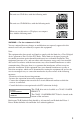
This unit uses CD-R discs with the following mark. This unit uses CD-ROM discs with the following mark. When you use this unit as a CD player, use compact discs with the following mark. WARNING — For the customers in U.S.A. You are cautioned that any changes or modifications not expressly approved in this manual could void your authority to operate this equipment. Note: This equipment has been tested and found to comply with the limits for a Class B digital device, pursuant to Part 15 of the FCC Rules.
Contents Introduction 5 Location and Function of Parts and Controls 6 Front Panel ......................................................................................... 6 Rear Panel .......................................................................................... 7 Precautions 8 Example of System Setup 9 Installing the Drive Unit into the Computer 10 Getting Started ................................................................................. 10 Setting the Jumpers ...............
Introduction The CDU948S is a drive unit for CD-R discs, which stores a maximum of 650 Mbytes of digital data. The drive unit has the following features: • Reads and writes data in each CD-ROM, CD-ROM XA and Multi-Session standard formats. • Reads standard CD-DA (“Red Book”) encoded discs, and reads and writes CD-R discs conforming to “Orange Book Part II.” • Supports the following write modes: Disc at once, Session at once, Track at once, Variable packet, Fixed packet and Multisession.
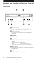
Location and Function of Parts and Controls Front Panel CD Caddy 1 Caddy insertion slot Accepts a caddy loaded with a CD-ROM or CD-R disc. 2 Emergency eject hole Insert a fine rod into this hole to eject a caddy manually in emergencies. 3 Eject button Ejects the caddy from the drive unit. 4 Busy indicator This indicator shows the unit’s status in various phases of operation.
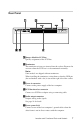
Rear Panel 1 Jumper block for SCSI bus Specify assignment of the SCSI bus. 2 Terminators The terminator resistors are inserted into the sockets. Remove the resistors when the SCSI bus is to be terminated externally. Note: Some models are shipped without terminators. When installing the terminators, orient them so that the GND pin (the end marked with a dot) is toward the right side of the socket. 3 Power-in connector Connect to the power supply of the host computer.
Precautions ■ Installation • Avoid placing the drive in a location subject to: – high humidity – high temperature – excessive dust – mechanical vibration – direct sunlight. We recommend to use the drive in a horizontal position. Do not use it in a tilted position. ■ Operation • Do not move the drive during operation. This may cause it to malfunction during reading or writing. • Avoid exposing the drive to sudden changes in temperature as condensation may form on the lens inside the drive as a result.
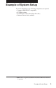
Example of System Setup To use the CD-R device, the following components are required: • Computer (IBM-PC/AT* compatible) • SCSI-Host adapter • SCSI-Interface cable (50 to 50 pin flat cable) • Software (Device driver, utilities) * IBM-PC/AT is a registered trademark of International Business Machines Corporation.
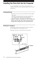
Installing the Drive Unit into the Computer As you go through this section, you may wish to refer to your computer’s manual for a more detailed description of how to install internal drives. Getting Started • Prepare the necessary parts and tools that have not been supplied: – Screwdriver – four screws 3 mm in diameter (Screws must not extend more than 4.0 mm into the side panels or the bottom plate.) – two mounting rails if your computer has mounting tracks.
Remove the jumper to set to OFF, and install the jumper to set to ON. The recommended jumper is AMP* Shunts (14227-1), JAE** Short Socket (PS-2SH4-1) or equivalent. The following table shows the function of each jumper. Jumper DEVICE TYPE ID SELECT Function The setting of this jumper determines whether the SCSI device type code in the inquiry data is WO or CD-ROM. ON: WORM OFF: CD-ROM Assign the drive unit’s ID number by setting these jumpers to ON or OFF.
Opening the Computer 1 If your computer has its rear side covered by a plastic panel attached with plastic hook pad, pull it off. 2 Remove the cover mounting screws. 3 Remove the cover of the computer.
Connecting the Drive Attach one end of the flat cable (SCSI cable) to the connector on the rear of the CD-R drive. Note: The red edge of the flat cable should be positioned next to the power supply connector. It is important that this cable be connected firmly and correctly.
■ Audio output connector The audio output connector recommended is Molex 5159PBT contacts and 5051-04 housing or 5103 PBT contacts and 5102-04 housing. Pin assignment Mounting the Drive 1 Route the flat cable through the drive bay from the front of the computer and insert the CD-R drive into the bay as shown. Secure the CD-R drive to the frame by using the prepared screws.
2 Locate an available power supply cable inside your computer and connect it to the power supply connector on the rear of the CD-R drive as shown. +- +- Caution: Improper connection may damage the drive and void the warranty. ■ Frame ground When normally installed, the drive unit is not in contact with the host computer directly and should be grounded. Connect the frame ground tab to one of the host computer’s ground cables.
Host Adapter Installation Connect the free end of the flat cable to the existing SCSI host adapter card and install the host adapter in the computer by inserting it securely in a system expansion slot. Refer to the operating instructions of the host adapter for complete instructions on its installation and the assignment of its switches. No t e s : • The red edge of the flat cable must be closest to pin number 1 of the interface card connector.
Termination • If the CD-R drive is connected at the end of the SCSI chain, keep the drive terminator mounted at the drive. • If the CD-R drive isn’t the last device at the SCSI bus, remove the termination from the CD-R drive and make sure that the last device at the SCSI bus has a proper termination installed. • Be aware that the SCSI bus needs to be terminated at each end of the SCSI bus cable.
Installing the Software Driver MSCDEX and the device driver for an ordinary SCSI CD-ROM drive can be used when using the CDU948S as a SCSI CD-ROM drive. Use the device driver for a CD-R drive when using the CDU948S as a recordable drive. Be sure to install the device driver before operating the drive. Refer to the manual supplied with the host adapter for instructions.
Using Discs and Caddies Loading a Caddy with a Disc 1 To open the caddy lid, press the tabs on the both sides of the caddy at the end opposite to the shutter. 2 Set a disc, with its label upward, in the caddy. Be careful not to touch the recording surface when setting a CDR disc in the caddy. Data cannot be recorded if the recording surface is contaminated.
3 Close the lid firmly. Important: • Do not drop the disc or the caddy. • The caddy is designed so that its shutter automatically opens when it is inserted into the drive unit. Do not open the shutter manually and touch the disc. • Data cannot be recorded if the recording surface is contaminated. • The caddy is precisely adjusted at the factory. Do not disassemble it.
Storing Discs and Caddies • Remove the caddy from the drive unit before moving the drive. • Do not store the disc and caddy in a location subject to: – high humidity – high temperature – excessive dust – direct sunlight Care of Discs • Hold the disc by its edge. Do not touch the surface. • Wipe the CD-ROM disc with the optional CD cleaner to clean it. • Do not wipe a CD-R disc with a cleaner before recording data. To avoid scratching the recording surface, blow away dust using an air blower.
Operating the Drive Make sure that the application software is installed in the host computer before using the drive. Starting Up 1 Turn on the power supply. 2 Insert the caddy into the drive slot with the disc’s label facing up, and push it partially into the drive until the automatic loading mechanism pulls the caddy in. Important: When inserting the caddy, let the automatic loading mechanism pull it into the drive by itself. Do not hold onto the caddy or attempt to overpower the loading mechanism.
In such a case, eject the caddy and re-insert it properly. If the busy indicator remains lit amber, consult your dealer or qualified service personnel. The busy indicator also lights amber during audio play. However, this is not a malfunction. Ejecting a Caddy 1 Turn on the power supply. 2 Press the eject button on the drive unit. CD Caddy No te s : • The eject button does not work if it is disabled by the software.
■ Ejecting a caddy manually in an emergency In the event of electrical or mechanical failure of the drive unit, a manual emergency eject is provided to allow removal of the caddy from the drive unit. 1 Turn off the power of your computer. 2 Insert a pointed object, such as a paper clip, into the emergency eject hole, and push with hand. (Typical required force is 59N [6.0kg]) CD Caddy After removing the caddy from the drive unit, consult your dealer or qualified service personnel.
Specifications ■ General Host interface Read Function Acceptable discs: Write Function Applied Format: Writing Method: Cache memory(R/W) Disc diameter: Rotational speed Innermost track: Outermost track: SCSI-2, single ended, 50 pin CD-ROM mode-1 data discs CD-ROM XA discs CD-Audio discs Audio-combined CD-ROM discs CD-I discs CD-I Ready Discs Photo CD (Single and Multi session) Video CD CD-R discs (Conforming to “Orange Book Part II”) CD-ROM Mode-1 CD-ROM XA CD-Audio Audio-combined CD-ROM CD-I Video CD
■ Drive performance Data transfer rate Sustained rate: SCSI Interface Burst rate: Access time Full stroke: Average: 150 kbytes/s (1x) 300 kbytes/s (2x) 600 kbytes/s (4x) 1200 kbytes/s (8x) 5 Mbytes/s (asynchronous) 10 Mbytes/s (synchronous) 500 ms (typical/1x) 450 ms (typical/2x) 400 ms (typical/4x) 350 ms (typical/8x) 350 ms (typical/1x) 300 ms (typical/2x) 250 ms (typical/4x) 220 ms (typical/8x) ■ Reliability Read error rate (includes retry, normal disc) L-EC on: 1 Block / 10 12 bits (double) L-EC off
Non-operating Transportation Shock Operating Non-operating Transportation ■ Dimensions and weight Dimensions Mass 19.6 m /s2 (2 G o-p) at 7 Hz to 300 Hz 1.44 m2 /s3 -Hz (0.015 G2 /Hz) at 5 Hz to 50 Hz Read: 49 m /s2 (5 G o-p) at 11 ms half sine wave (includes 5 retries) Write:4.9 m/s2 (0.5 G o-p) at 11ms half sine wave 490 m /s2 (50 G o-p) at 11ms half sine wave 76 cm drop (with standard individual package) 146.0 x 41.4 x 203.0 mm ( w / h / d ) (5 3/4 x 1 5/8 x 8 inches) 1.
■ Laser Type Wave length Output power Beam divergence Semiconductor laser GaAlAs 778 to 787nm (at 25 ˚C ± 2 ˚C) 2.5 mW (Read) 60 mW (Write) 60 degree ■ Supplied accessory User’s Guide Disc Caddy OPA-2000 (1 each) (1 each) ■ Optional accessories CD ROM discs: Additional caddies: YHDS-50 “CD-ROM Test Disc Type 1.3” (equivalent to YHDS-4) YHDS-100 “CD-ROM Test Disc Type 2.0" (audio-combined) OPA-2000 ■ Crystal frequency 33.8688 MHz 34.
■ Dimension diagram CD Caddy Important: Screws must not extend more than 4.0mm into the side panels or the bottom plate.