2-654-967-12 (1) Video Projector Operating Instructions VPL-HS51A VPL-HS60 © 2005 Sony Corporation
WARNING To reduce the risk of fire or electric shock, do not expose this apparatus to rain or moisture. To avoid electrical shock, do not open the cabinet. Refer servicing to qualified personnel only. This symbol is intended to alert the user to the presence of uninsulated “dangerous voltage” within the product’s enclosure that may be of sufficient magnitude to constitute a risk of electric shock to persons.
For the customers in Canada (VPL-HS60 only) This Class B digital apparatus complies with Canadian ICES-003. Voor de klanten in Nederland Gooi de batterij niet weg maar lever deze in als klein chemisch afval (KCA). The socket-outlet should be installed near the equipment and be easily accessible. CAUTION RISK OF EXPLOSION IF BATTERY IS REPLACED BY AN INCORRECT TYPE. DISPOSED OF USED BATTERIES ACCORDING TO THE LOCAL RULES.
Table of Contents Precautions .........................................6 Signal Menu ..................................... 39 Function menu ................................. 40 Connections and Preparations Unpacking ..........................................7 Step 1: Installing the Projector ...........8 Before Setting Up the Projector ... 9 Installing the Projector and a Screen ...........................10 Step 2: Connecting the Projector .....13 Installation Menu .............................
Precautions On safety • Check that the operating voltage of your unit is identical with the voltage of your local power supply. • Should any liquid or solid object fall into the cabinet, unplug the unit and have it checked by qualified personnel before operating it further. • Unplug the unit from the wall outlet if it is not to be used for several days. • To disconnect the cord, pull it out by the plug. Never pull the cord itself. • The wall outlet should be near the unit and easily accessible.
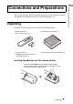
This section describes how to install the projector and screen, how to connect the equipment from which you want to project the picture, etc.
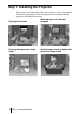
Step 1: Installing the Projector The projector’s lens shift feature allows you to choose a variety of installation locations for your projector. You can enjoy home entertainment with this projector in the following situations. Enjoying home theater Watching sports, etc.
Very dusty and extremely smoky Do not place the projector in the following situations, which may cause malfunction or damage to the projector. Poorly ventilated Make a special attention to the following while using the projector. Do not block the ventilation holes. Highly heated and humid Ventilation holes (intake) Ventilation holes (exhaust) Tip For details on the location of the ventilation holes (intake or exhaust), see “Location of Controls” on pages 60 to 62.
Installing the Projector and a Screen The installation distance between the projector and a screen varies depending on the size of the screen. 1 Determine the installation position of the projector and screen. You can obtain a good quality picture if you position the projector with the center of the lens within the areas indicated in the gray areas in the illustration. Use the values a, b, c, d and e in the table on page 11 as a guide.
When using the 16:9 aspect ratio screen 40 60 80 100 120 150 180 200 a (minimum) 1170 (46 1/8) 1770 (69 3/4) 2380 (93 3/4) 2980 3580 (117 3/8) (141) 4490 5390 6000 (176 7/8) (212 1/4) (236 1/4) b (maximum) 1790 (70 1/2) 2710 3630 (106 3/4) (143) 4540 5460 (178 7/8) (215) 6830 (269) 8210 9120 (323 3/8) (359 1/8) c 498 (19 5/8) 747 (29 1/2) 996 (39 1/4) 1245 (49 1/8) 1494 (58 7/8) 1868 (73 5/8) 2241 (88 1/4) 2491 (98 1/8) d 443 (17 1/2) 664 (26 1/4) 886 (35) 1107 (43 5/8) 132
2 Position the projector so that the lens is parallel to the screen. Top view Screen 3 Project an image on the screen and adjust the picture so that it fits the screen. (1 page 17) To project an image, connect video equipment to the projector. (1 page 13) Note When using a screen with an uneven surface, stripes pattern may rarely appear on the screen depending on the distance between the screen and the projector or the zooming magnifications. This is not a malfunction of the projector.
When making connections, be sure to do the following: • Turn off all equipment before making any connections. • Use the proper cables for each connection. • Insert the cable plugs properly; plugs that are not fully inserted often generate noise. When pulling out a cable, be sure to pull it out from the plug, not the cable itself. • Refer to the operating instructions of the connected equipment.
To connect to a DVD player/recorder equipped with HDMI output You can enjoy better picture quality by connecting a DVD player/recorder equipped with HDMI output to the HDMI input of the projector. Rear of the projector AV amplifier Speakers DVD player/recorder, etc., with the HDMI output HDMI Y PB/CB PR/CR VIDEO INPUT to HDMI output HDMI cable (not supplied) : Video signal flow Note When the 720p signals (signals preset with memory Nos.
Connections and Preparations Connecting to Video Equipment You can connect a DVD player/recorder which is not equipped with component video connectors, hard disk video recorder, VCR or laser disk player. See also the instruction manual of each equipment.
Connecting to a Computer Rear of the projector Computer PR/CR VIDEO INPUT S VIDEO INPUT A to monitor output HD D-sub 15-pin cable (not supplied) : Video signal flow Tip Set “Input A Signal Sel.” in the Setup menu to “Auto” or “Computer.” If the input signal does not appear properly, set it to “Computer.” Note If you set your computer, such as a notebook type, to output the signal to both your computer’s display and an external monitor, the picture of the external monitor may not appear properly.
Connections and Preparations Step 3: Adjusting the Picture Size and Position Project an image on the screen and then adjust the picture position.
2 Press the I/1 (on/standby) switch to turn on the projector. The ON/STANDBY indicator flashes in green, then lights. Lights in green. ON/ STANDBY 3 Turn on the equipment connected to the projector. Refer to the operating instructions of the connected equipment. 4 Press INPUT to project the picture on the screen. Each time you press the button, the input indication changes.
1/2H 1H 1/2H Top view : Picture position when moving the picture to the left at maximum : Picture position when moving the picture to the right at maximum To adjust the vertical position Turn the LENS SHIFT dial up or down. The picture moves up or down by a maximum of the screen size from the center of the lens.
Note When you use the horizontal and vertical lens shift features at the same time, you can move the picture vertically by a maximum of half of the screen size. 6 Adjust the picture size using the zoom ring. Zoom ring 7 Adjust the focus using the focus ring. Focus ring To adjust the tilt of the installation surface If the projector is installed on an uneven surface, use the adjusters to keep the projector level. Turn to adjust.
You can select one of fifteen languages for displaying the menu and other onscreen displays. The factory default setting is English. LIGHT DYNAMIC 2 INPUT STANDARD CINEMA PICTURE MODE USER 1 USER 2 USER 3 4-6 ENTER APA ADJ PIC MENU WIDE MODE RCP RESET 3 REAL COLOR PROCESSING Tip You can operate the menu using the M/m/
4 Press M or m to select the Setup menu, and press , or ENTER. The setting items of the selected menu appears. Picture Signal Status : Language : Input-A Signal Sel. : Color System : On English Auto Auto Function Installation Setup or ENTER Information Sel: 5 Set: Back: Exit: Press M or m to select “Language,” and press , or ENTER. Picture Signal Status : Language : Input-A Signal Sel.
Projecting Projecting the Picture on the Screen VPL-HS60 Focus ring Zoom ring Remote control detector VPL-HS51A LIGHT DYNAMIC Remote control detector INPUT STANDARD CINEMA PICTURE MODE USER 1 USER 2 USER 3 ENTER Zoom ring Focus ring 1 Plug the AC power cord into a wall outlet. The ON/STANDBY indicator lights in red and the projector goes into standby mode. Lights in red. ON/ STANDBY 2 Press the I/1 (on/standby) switch to turn on the projector.
4 Press INPUT repeatedly to select the input you want to project on the screen. Display the indication of the input you want. Example: To view the picture from the video equipment connected to the VIDEO INPUT jack.
6 Turn the focus ring to adjust the focus. Adjust to obtain sharp focus. Projecting Focus ring Turning Off the Power 1 Press the I/1 (on/standby) switch. A message “POWER OFF?” appears on the screen. 2 Press the I/1 switch again. The ON/STANDBY indicator flashes in green and the fan continues to run to reduce the internal heat. First, the ON/STANDBY indicator flashes quickly, during which you will not be able to light up the ON/STANDBY indicator with the I/1 switch.
Selecting the Wide Screen Mode You can enjoy various wide screen mode according to the video signal received. You can also select it using the menu. (1 page 39) LIGHT DYNAMIC INPUT STANDARD CINEMA PICTURE MODE USER 1 USER 2 USER 3 ENTER APA ADJ PIC MENU WIDE MODE RCP RESET WIDE MODE button REAL COLOR PROCESSING Press WIDE MODE. Each time you press the button, you can select the “Wide Mode” setting. Full A picture squeezed to 4:3 is displayed with the correct aspect ratio.
Normal A picture with normal 4:3 aspect ratio is displayed in the center of the screen to fill the vertical screen size. Projecting Wide Zoom A 4:3 aspect ratio picture is enlarged and the upper and lower portions of the picture are compressed to fit the 16:9 screen. Use this mode to view news, variety shows, etc. Zoom A normal 4:3 aspect ratio picture is enlarged vertically and horizontally in the same ratio to fill the 16:9 screen. This mode is ideal for viewing a wide-format movie.
Notes on selecting the wide screen mode • Select the wide screen mode taking into account that changing the aspect ratio of the original picture will provide a different look from that of the original image. • Note that if the projector is used for profit or for public viewing, modifying the original picture by switching to the wide mode may constitute an infringement of the rights of authors or producers, which are legally protected.
Selecting the Picture Viewing Mode LIGHT DYNAMIC INPUT STANDARD CINEMA PICTURE MODE USER 1 USER 2 USER 3 ENTER APA WIDE MODE ADJ PIC MENU RCP RESET PICTURE MODE buttons DYNAMIC STANDARD CINEMA USER 1, 2 and 3 REAL COLOR PROCESSING Press one of the PICTURE MODE buttons (DYNAMIC, STANDARD, CINEMA and USER 1, 2 and 3). DYNAMIC Select for enhanced picture sharpness in bright environment. STANDARD Recommended for normal viewing condition in your home.
Adjusting the Picture Quality You can adjust the picture quality that suits your taste by selecting the adjustment items with the remote control. The adjusted data can be stored in each picture mode. LIGHT INPUT DYNAMIC STANDARD CINEMA PICTURE MODE USER 1 USER 2 USER 3 ENTER ADJ PIC button APA WIDE MODE ADJ PIC MENU RCP RESET REAL COLOR PROCESSING BRIGHT CONTRAST + – + – CONTRAST +/– button BRIGHT +/– button 1 Press ADJ PIC.
Example: To adjust the contrast Projecting Contrast For details on each adjustment, see “Adjust Picture” in the Picture menu. (1 page 37) 2 Make the setting or adjustment on an item. When changing the adjustment level To increase the value, press M or ,. To decrease the value, press m or <. When changing the setting Press M or m to change the setting. To adjust contrast and brightness Press CONTRAST +/– on the remote control to adjust the contrast.
Adjusting the Picture Using Real Color Processing The Real Color Processing (RCP) feature allows you to adjust the color and hue of each target of the projected picture you specify independently. You can thus obtain a picture more suitable to your taste.
RCP (Real Color Processing) Sel : Red Adjust Adjust 0 0 Set : Projecting Color Select : Position : Range : RCP Color : RCP Hue : Exit : Reference palette 2 Press M or m to select “Position” or “Range,” and specify it more delicate color and color range you want to adjust using < or ,. RCP (Real Color Processing) Color Select : Position : Range : RCP Color : RCP Hue : Sel : Red Adjust Adjust 0 0 Set : Exit : 4 Adjust the color of the specified portions.
Using the Menus This section describes how to make various adjustments and settings using the menus. Operation through the Menus The projector is equipped with an on-screen menu for making various adjustments and settings. Some of the adjustable/setting items are displayed in a pop-up menu, in a setting menu or adjustment menu with no main menu, or in the next menu window. If you select an item name followed by an arrow (B), the next menu window with setting items appears.
2 Press M or m to select a menu item, and press , or ENTER. The items that can be set or adjusted with the selected menu appear. The item presently selected is shown as a yellow button. Status : Language : Input-A Signal Sel. : Color System : Picture Signal On English Au t o Au t o Installation Setup Information Sel: 3 Set: Back: Exit: Press M or m to select an item you want to set or adjust and press , or ENTER.
Next menu window Setting items Picture Signal Function Installation Setup Information Adjust Picture Cinema Contrast : 80 Brightness : 50 Color : 50 Hue : 50 Sharpness : 50 Black Level Adj. : Off Gamma Correction : O f f Color Temp : Low DDE : Film Cinema Black Pro Sel: 4 Set: Back: Exit: Make the setting or adjustment on an item. When changing the adjustment level To increase the value, press M or ,. To decrease the value, press m or <. Press ENTER to restore the original screen.
Picture Menu The Picture menu is used for adjusting the picture. Adjust Picture menu Signal Cinema Picture Off Signal Function Function Installation Installation Setup Setup Information Information Sel: Set: Back: Exit: Adjust Picture Contrast : Brightness : Color : Hue : Sharpness : Black Level Adj.
Item Description Adjust Picture Black Level Adj (Adjust) Emphasizes black color to produce a bolder “dynamic” picture. Set according to the input signal source. Off: Cancels this feature. Low: Gives lower emphasis to the black color. High: Gives higher emphasis to the black color. Gamma Correction Selects a favorite tone from three options. Off: The feature does not function. Gamma1: Makes the dark portion of a scene a little brighter.
Signal Menu The Signal menu is used to adjust the input signal. You can adjust the size of the picture, and select wide screen mode, etc .
Function menu The Function menu is used for changing the settings of the function of the projector. Picture Signal Smart APA : Auto Input Search : Standby Mode : Power Saving: On Off Standard Off Function Installation Setup Information Sel: Set: Back: Exit: Item Description Smart APA With this item set to On, the APA function works automatically for a signal input from a computer so that the picture can be seen clearly.
Installation Menu The Installation menu is used for changing the installation settings. Picture Function 0 Off Blue On Off Using the Menus Signal V Keystone : Image Flip : Background : Illumination : High Altitude Mode : Network Setting Installation Setup Information Sel: Set: Back: Exit: Item Description V Keystone Corrects the vertical trapezoidal distortion of the picture. Sets a lower value (– direction) when the bottom of the trapezoid is longer than the top ( ).
Setup Menu The Setup menu is used to change the factory preset settings. Picture Signal Status : Language : Input-A Signal Sel. : Color System : On English Au t o Au t o Function Installation Setup Information Sel: Set: Back: Exit: Item Description Status Set to Off to turn off the on-screen displays except for the menus, message when turning off the power, and warning messages. Language Selects the language used in the menu and on-screen displays.
Information Menu The Information menu is used to display the horizontal and vertical frequencies of the input signal, used time of the lamp, etc. fH : fV : 33.75kHz 60.00Hz No.7 1080/60i Memory No. Lamp Timer : 10H Signal type Signal Using the Menus Picture Function Installation Setup Information Sel: Exit: Item Description fH Displays the horizontal frequency of the input signal. fV Displays the vertical frequency of the input signal. (Memory No.
Adjusting Picture Quality of a Signal from the Computer You can automatically adjust to obtain the clearest picture when projecting a signal from the computer. 1 2 Project a still picture from the computer. Press the APA (Auto Pixel Alignment) button. When the picture is adjusted properly, “complete!” appears on the screen. Notes • When “Smart APA” is set to “On,” the APA function is automatically activated. • Press the APA button when the image appears on the whole display area of the computer.
Others This section describes how to solve the problems, how to replace a lamp and air filter, etc. If the projector appears to be operating erratically, try to diagnose and correct the problem using the following instructions. If the problem persists, consult with qualified Sony personnel. Power Symptom The power is not turned on. Cause and Remedy c Wait for about one minute before turning on the power. (1 page 25) c Close the lamp cover securely. (1 page 48) c Close the air filter cover securely.
On-screen display Symptom Cause and Remedy On-screen display does not appear. c Set “Status” in the Setup menu to “On.” (1 page 42) Remote control Symptom Cause and Remedy The remote control does not work. c Batteries could be weak. Replace with new batteries. (1 page 7) c Insert the batteries with correct polarities. (1 page 7) Warning Indicators The LAMP/COVER or TEMP/FAN indicator on the control panel lights up or flashes if there is any trouble with your projector.
Message Lists Warning messages Message Cause and Remedy c Turn off the power. c Check to see if nothing is blocking the ventilation holes. Frequency is out of range! c Input a signal that is within the acceptable range of the frequency. c Set the output signal on an external monitor of the connected computer to SVGA. c Set “Input-A Signal Sel.” in the Setup menu to “Computer”. (1 page 42) Please check Input-A Signal Sel. c Set “Input-A Signal Sel.
Replacing the Lamp 3 Loosen a screw with the Philips screwdriver 1, then open the lamp cover 2. 4 Loosen the three screws on the lamp unit with the Philips screwdriver 1. Pull out the lamp unit by the handle 2. 5 Insert the new lamp all the way in until it is securely in place 1. Tighten the three screws 2. Fold down the handle. 6 Close the lamp cover and tighten the screw. 7 8 Turn the projector back over. The lamp used for the light source has a certain life.
Check that the ON/STANDBY indicator lights in red. 9 Point the remote control at the projector and press the following buttons on the remote control in the following order for less than five seconds each: RESET, <, ,, ENTER. The air filter should be replaced periodically. When “Please replace the filter.” appears on the screen, replace the air filter immediately. Notes • Replacing the air filter is very important to maintain the high efficiency of the projector and to prevent a malfunction.
4 Insert the new air filter into the projector. 5 Replace the filter cover. Notes • The projector will not turn on unless the filter cover is securely closed. • To erase the message displayed on the screen, press any button on the remote control or the control panel.
Specifications Input General Video input VIDEO: phono type Composite video: 1 Vp-p±2 dB sync negative (75 ohms terminated) S VIDEO: Y/C mini DIN 4-pin type Y (luminance): 1 Vp-p±2 dB sync negative (75 ohms terminated) C (chrominance): burst 0.286 Vp-p ±2 dB (NTSC) (75 ohms terminated) burst 0.
Operating temperature 0°C to 35°C (32°F to 95°F) Operating humidity 35% to 85% (no condensation) Storage temperature –20°C to 60°C (–4°F to 140°F) Storage humidity 10% to 90% Supplied accessories Remote control RM-PJHS50 (1) Size AA (R6) batteries (2) AC power cord (1) Air filter (for replacement) (1) Operating Instructions (1) CD-ROM (Application software) (VPL-HS51A only) (1) Design and specifications are subject to change without notice. Safe regulations VPL-HS60: UL60950, CSA No.
Warning on power connection Use a proper power cord for your local power supply.
Item Input signal Video or S video (Y/C) Component Video GBR Computer z z (preset memory numbers 3,4,7,8,9 only) z (preset memory numbers 3,4,7,8,9 only) – Advanced Iris z z z z z Lamp Control z z z z z DDE Cinema Black Pro HDMI z (preset memory numbers 3,4,7,8 only) z : Adjustable/can be set – : Not adjustable/cannot be set Signal menu Item Input signal Video or S video (Y/C) Component Video GBR Computer HDMI Dot Phase – – – z – H size – – – z – Shift – z (prese
Preset Signals Memory No. Preset signal fH (kHz) fV (Hz) Sync H Size HDMI input VIDEO/60 60 Hz 15.734 59.940 – – – 2 VIDEO/50 50 Hz 15.625 50.000 – – – 3 480/60i 480/60i 15.734 59.940 SonG/Y or composite sync – z 4 575/50i 575/50i 15.625 50.000 SonG/Y or – composite sync/ composite video z 5 480/60p 480/60p (Progressive NTSC) 31.470 60.000 SonG/Y – z 6 575/50p 575/50p (Progressive PAL) 31.250 50.000 SonG/Y – z 7 1080/60i 1035/60i, 1080/60i 33.750 60.
Memory No. 31 Preset signal 800 u 600 fH (kHz) fV (Hz) Sync H Size HDMI input VESA 56 35.156 56.250 H-pos, V-pos 1024 – 32 VESA 60 37.879 60.317 H-pos, V-pos 1056 – 33 VESA 72 48.077 72.188 H-pos, V-pos 1040 – 34 VESA 75 (IBM M5) 46.875 75.000 H-pos, V-pos 1056 – 35 VESA 85 53.674 85.061 H-pos, V-pos 1048 – 36 832 u 624 Mac 16 49.724 74.550 H-neg, V-neg 1152 – 37 1024 u 768 VESA 60 48.363 60.004 H-neg, V-neg 1344 – 38 VESA 70 56.476 70.
Ceiling Installation Use the PSS-610 Projector Suspension Support when you install the projector on a ceiling. The projection distances for ceiling installation are shown below.
When using the 4:3 aspect ratio screen Unit: mm (inches) Screen Size (inches) 40 60 80 a Minimum Distance 1560 (61 1/2) 2300 (90 5/8) 3040 3780 4510 5620 6730 (119 3/4) (148 7/8) (177 5/8) (221 3/8) (265) Maximum Distance 2320 (91 3/8) 3450 4570 (135 7/8) (180) 5690 6810 8490 10170 11290 (224 1/8) (268 1/4) (334 3/8) (400 1/2) (444 5/8) x Minimum Distance 305 (12 1/8) 457 (18) 610 (24 1/8) 762 (30) 914 (36) 1143 (45) 1372 (54 1/8) 1524 (60) b+685 (b+27) b+989 (b+39) b+1294 (b+51) b+
Front view Distance between the ceiling and the surface of the mount bracket Using adjustment pipe (b): 150/175/200 mm (6 / 7 / 7 7/8 inches) Using adjustment pipe (c): 250/275/300 mm (9 7/8 / 10 7/8 / 11 7/8 inches) 250 (9 7/8) 125 (5) Others The bottom surface of the mount bracket Ceiling Center of the supporting pole 75 (3) Center of the lens 66 (2 5/8) Side view 216.5 (8 5/8) 152.5 (6 1/8) Center of the lens Front of the cabinet 135.5 (5 3/8) 224.5 (8 7/8) 14.
Location of Controls Front You can use the buttons on the control panel with the same names as those on the remote control to operate the projector.
Rear Air fliter cover (1 page 49) Others Air filter (1 page 49) Ventilation holes (intake) (1 page 9) TRIGGER USB HDMI Y PB/CB PR/CR VIDEO INPUT S VIDEO INPUT A AC IN TRIGGER jack (minijack) Outputs a 12 V signal when the power is on. USB connector (VPL-HS51A only) Connects to a computer with the USB cable (A y mini-B: not supplied) when performing “Gamma Correction” using the specified controller, “ImageDirector.
Bottom Adjusters (1 page 20) Lamp cover (1 page 48) Ventilation holes (intake) (1 page 9) 62 Location of Controls Projector suspension support attachment holes (1 page 58)
Remote Control Infrared transmitter INPUT button (1 page 24) LIGHT DYNAMIC PICTURE MODE buttons (1 page 29) I/1 (on/standby) switch (1 page 18) INPUT STANDARD CINEMA PICTURE MODE USER 1 USER 2 USER 3 M/m/
Index A Adjust Picture .......................................... 37 Adjust Signal ........................................... 39 Adjuster ................................................... 20 Adjusting picture quality ...................................... 30 Picture Quality of a Signal from the Computer ..................................... 44 picture size and position ...................... 17 picture size/position ............................ 17 picture size/shift ..................................
R Real Color Processing .......................32, 38 Remote control inserting the batteries .............................7 location of controls ..............................63 Replacing the Lamp ................................48 Reset resettable items ....................................36 resetting the items ................................36 Others S Selecting the menu language ...................21 Setup menu ..............................................42 Sharpness .................................
Printed on 100% recycled paper. Power consumption in standby is 0.5 W. Lead-free solder is used for soldering. Halogenated flame retardants are not used in cabinets and printed wiring boards. Polystyrene foam for the packaging cushions is not used in packaging. 100% recycled paper is used for the carton.