FLAT WIDE DISPLAY MONITOR FWD-S47H1/S42H1 PROTOCOL MANUAL (For Customer)
Table of Contents 1. RS-232C 3. ID Talk 1. Communication Parameters................................................ 1 1. Default Setting.................................................................. 33 2. Pin Assignment.................................................................... 1 2. Setting Items...................................................................... 34 3. Communication Data Format.............................................. 1 3. Packet Structure...........
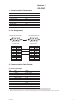
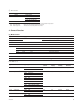
Section 1 RS-232C 1. Communication Parameters Communication method RS-232C Synchronous method Asynchronous Baud rate 9600bps Character length 8bit Parity None Start bit length 1bit Stop bit length 1bit Flow control None 2. Pin Assignment Monitor side (D-sub 9-pin) 5 4 9 3 8 2 7 Host side (D-sub 9-pin) 1 5 6 _ External view _ Pin No. 1 2 3 4 5 6 7 8 9 4 9 3 8 2 7 1 6 _ External view _ Function NC TXD RXD NC GND NC NC NC NC Pin No.
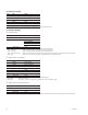
(b) Enquiry message No. Item Value 1 Header 0x83: Enquiry 2 Category 0xXX 3 Function 0xXX 4 Data1 0xFF 5 Data2 0xFF 6 Check Sum 0xXX * Check Sum: Sum total of 1 to X, lower one-byte data is validated when a value exceeds 255 (1byte). (c) Answer message 1 Control answer No.
4 Error answer No. Item Value 1 Header 0xE0: Answer 2 Answer* 0x00: No Function Error 0x01: Check Sum Error 0x02: Data Length Error 3 Check Sum 0xXX * 0x00: No Function Error 0x01: Check Sum Error 0x02: Data Length Error Packet header,category or function code are not included in this protocol. Check sum value of received packet is not correct. The data size of received packet is not correct. 4.
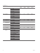
Code Table (1-a) [a]Function [b]Range/Switch Code Command Control Enquiry Standby Power On 0x06 0x00 Auto Yes Yes Disable Enable 0x01 NTSC Color System 0x02 NTSC4.
Code Table (1-a) [a]Function [b]Range/Switch Code Command Control Enquiry Standby Power On 0x26 0x00 OFF Yes Yes Disable Enable 0x01 ON Auto Shut OFF 0x27 Auto Screen Adjust 0x30 OFF ON Yes 0x00 OFF P&P 0x02 PinP Left (P&P)/Main (PinP) Right (P&P)/Sub (PinP) 0x02 Swap 0x32 Picture Size (P&P) 0x00-0x0E Yes Yes Disable Enable 0x33 Sub Picture Size (PinP) 0x00 Large Yes Yes Disable Enable
Code Table (1-a) [b]Range/Switch Code Control Command Enquiry Standby Power On 0x40 0x00 OFF Yes Yes Disable 0x01 All White ON Screen Saver Enable 0x02 Sweep ON 0x03 Standby 0x43 Back Light 0x00-0x64 Yes Yes Disable Enable 0x44 Logo Illumination 0x00 Logo Off Yes Yes Enable Enable 0x01 Logo On (Low) 0x02 Logo On (High) 0x45 0x00 Main + Remocon 0x01 Main Control Mode Ye
Code Table (1-a) [a]Function [b]Range/Switch Code Command Control Enquiry Standby Power On 0x67 0x00 Done Yes No Enable Enable 0x01 Error 1 (UART Commu.
Code Table (1-a) [a]Function [b]Range/Switch Code Command Control Enquiry Standby Power On 0x7E 0x00 OFF Yes Yes Enable Enable 0x01 ON (Default) Yes Yes Disable Enable Yes Yes Enable Enable On Screen Logo 0x02 Reserved 0x7F 0x00 OFF 0x01 ON 0x81 0x00-0x78 1sec x Data *1: *2: *3: *4: *5: LED Power On Delay Auto Signal Detect becomes Disable. When Option Slot is connected, Option command is Enable.
6.
Year Set Syntax Header Category Function Data1 Data2 Check Sum Control 0x8C 0x00 0x7B 0x02 Year: 0x00-0x63 0xXX Syntax Header Category Function Data1 Data2 Check Sum Enquiry 0x83 0x00 0x7B 0xFF 0xFF 0xFC Answer Header Answer Check Sum Control 0x70 0x00 0x70 Completed 0x70 0x01 0x71 Limit Over 0x70 0x02 0x72 Limit Under 0x70 0x03 0x73 Command Canceled Answer Header Answer Return to Data Siz
Code Table (1-e) Week Select 0x00 Sunday 0x01 Monday 0x02 Tuesday 0x03 Wednesday 0x04 Thursday 0x05 Friday 0x06 Saturday On Timer, Off Timer Syntax Header Category Function Data1 Data2 Data3 Check Sum Control 0x8C 0x00 Code Table (1-f) [a] 0x03 Hour: 0x00-0x17 Minute: 0x00-0x3B 0xXX Syntax Header Category Function Data1 Data2 Check Sum Enquiry 0x83 0x00 Code Table (1-f) [a] 0xFF 0xFF 0xXX Answer Header Answer Check Sum Co
(d) IP Address Setting IP Address Syntax Header Category Function Data1 Data2 Data3 Data4 Data5 Check Sum Address 0 0x00-0xFF Address 1 0x00-0xFF Address 2 0x00-0xFF Address 3 0x00-0xFF 0xXX Category Function Data1 Data2 Check Sum 0x00 0xFF 0xC3 Data2 Data3 Data4 Data5 Check Sum Control 0x8C 0x00 0x61 0x05 Address 0 0x00-0xFF Address 1 0x00-0xFF Address 2 0x00-0xFF Address 3 0x00-0xFF 0xXX Syntax Category Function Data1
Player IP Address Syntax Header Enquiry 0x83 Category Function Data1 Data2 Check Sum 0x00 0xFF 0x04 0x83 0xFF Answer Header Answer Check Sum Control 0x70 0x00 0x70 Completed 0x70 0x03 0x73 Command Canceled Answer Header Category Function Enquiry 0x8C 0x00 Data1 Code Table 0x05 (1-a)[a] Data2 Data3 Data4 Data5 Check Sum Address 0 0x00-0xFF Address 1 0x00-0xFF Address 2 0x00-0xFF Address 3 0x00-0xF
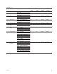
Code Table (2-a) [a]Function [b]Range/Switch code Command Control Enquiry Standby Power On 0x00 Contrast 0x00-0x64 Yes Yes Disable Enable 0x01 Brightness 0x00-0x64 Yes Yes Disable Enable 0x02 Chroma 0x00-0x32 Yes Yes Disable Enable 0x03 Phase 0x00-0x64 Yes Yes Disable Enable 0x04 Color Temp 0x00 Cool Yes Yes Disable Enable 0x01 Neutral 0x02 Warm Custom 0x03 0x09 Sharpness 0x00-0x
Code Table (2-a) [a]Function [b]Range/Switch code Command Control Enquiry Standby Power On 0x36 Default Volume Set 0x00-0x64 Yes Yes Enable Enable 0x37 Volume Select 0x00 Last Memory Yes Yes Enable Enable 0x01 Default Setting 0x38 0x32 50 0x46 70 0x64 100 Max Volume Set Yes Yes Enable Enable *1 Picture Mode = Vivid Only is Enabled. *2 Sound Mode = Custom Only is Enabled.
8.
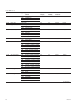
Code Table (3-b) [a]Function [b]Range/Switch code Command Control Enquiry Standby Power On 0x06 Auto Pixel Adjust 0xFF Execute Yes No Disable Enable 0x07 Dot Phase 0x00-0x1F Yes Yes Disable Enable 0x0B Multi Position 0x00 Yes Yes Disable Enable (2 x 2 ,1 x 2, 2 x 1)*1 0x01 Position1 Position2 0x02 Position3 0x03 Position4 0x00 Position1 0x0C Multi Position (3 x 3, 1 x 3
*1 Arrangement of Multi Position.
(b) Power On Batch Syntax Header Category Function Data1 Control 0x8C 0x00 0x85 0x03 Data2 Data3 Check Sum Input Select Code Table (1-a)[a] Volume Code Table (1-a)[b] 0xXX Syntax Header Category Function Data1 Data2 Check Sum Enquiry 0x83 0x00 0x85 0xFF 0xFF 0xXX Answer Header Answer Check Sum Control 0x70 0x00 0x70 Completed 0x70 0x01 0x71 Limit Over 0x70 0x02 0x72 Limit Under 0x70 0x03 0x73 Com
9.
(d) Soft Version (Main CPU/LAN) Syntax Header Category Enquiry 0x83 0x30 Answer Header Answer Enquiry 0x70 0x00 Function Data1 Data2 Check Sum Code Table (4-k) 0xFF 0xFF 0xB4 Return to Data Size Return Data1 Return Data2 Check Sum Code Table (4-k) Upper 8bit Data Lower 8bit Data 0xXX Completed Return Data1-Data2: 0x0000-0xFFFF (BCD Format) ex) In Version0.100, it is set to 01 and 00.
(f) Shutdown Log Syntax Enquiry Header Category 0x83 0x30 Answer Header Answer Function Data1 0x11 0xFF Data2 0xFF Return to Data Size Enquiry 0x70 0x00 0x02 Check Sum 0xC2 Return Data1 Check Sum Shutdown Log Code Table (4-c) 0xXX Completed Return Data1: 0x00-0xFF (g) Shutdown Log Clear Syntax Header Category Function Data1 Data2 Check Sum Control 0x8C 0x30 0x11 0x02 0x00 0xCF Answer Header
(i) Auto Input Detect Syntax Header Category Function Data1 Data2 Check Sum Enquiry 0x83 0x30 0x30 0xFF 0xFF 0xE1 Answer Header Answer Return to Data Size Return Data1 Return Data2 Return Data3 Return Data4 Return Data5 Enquiry 0x70 0x00 0x0C Input1 Input Type Code Table (4-e) Return Data6 Return Data7 Return Data8 Return Data9 Return Data10 Option1 Option Type Code Table
(j) Auto Panel Type Detect Syntax Enquiry Header Category 0x83 0x30 Function Data1 0x31 0xFF Data2 0xFF 0xE2 Header Answer Return to Data Size Return Data1 Enquiry 0x70 0x00 0x02 Code Table (4-h) Check Sum 0x72 Completed Code Table (4-i) Code Table (4-j) H_Resolution 0x0780 (1920) Input Quantity 0x05 Panel Type 0x00 Option Slot Quantity V
(k) Auto Plug Detect Syntax Header Category Function Data1 Data2 Check Sum Enquiry 0x83 0x30 0x32 0xFF 0xFF 0xE3 Answer Header Answer Return Data1 Return Data2 Return Data3 Enquiry 0x70 0x00 0x21 Panel Type Code Table (4-h) H_Resolution (H) Code Table (4-i) H_Resolution (L) Code Table (4-i) Return Data5 Return Data6 Return Data7 Return to Data Size Return Data4 V_Resolution (H) V_Resolution (L) Input Quantity Code Table (
10.
Section 2 SNMP 1. SNMP FWD-S42H1/S47H1 installs SNMP (Simple Network Management Protocol). SNMP is a standard protocol for network management that was standardized in IETF (Internet Engineer Task Force). By using SNMP, the management information of equipment connected to a network can be gotten via a network. The information of multiple equipment gotten using SNMP can also be unitarily managed by using SNMP management software.
2. Specifications of SNMP Installation The specifications of the SNMP agent installed in this unit are shown in below. . SNMP version: SNMPv1 . MIB definition: SMIv2 . Support PDU: GetRequesat SetRequest GetNextRequest Trap . Standard MIB to be installed: MIB-II 3. Installation The setting below is required to use the SNMP function of this unit. (Set according to your network environment and SNMP management environment.) . Community and its Community property .
4-1. Community A Community name is used as the password for SNMP access. The request received from an SNMP manager is accepted when the Community name contained in the request coincides with the Community name set. The request is rejected when the former does not coincide with the latter. A maximum of three Communities can be set. There are “Rights” and “Trap destinations” items in the property of Community. The property can be set for each set Community.
Editing of Community 1. Select the Community, you want to edit, from a drop-down list. 2. Click the [Edit] button. The “Community name”, “Rights”, and “Trap destinations” text boxes, and [Set|To|List] and [Cancel] buttons are validated. Edit the Community name when you want to edit a Community name. 3. Set the Rights of Community and the Trap destinations you want to edit. m . Click the [Cancel] button when you want to discard the setting during setting. .
5. MIB to Be Installed This unit installs MIB-2. MIB-2 is the most representative standard MIB. It is installed in various network products. The statistical information on the amount of network traffic or the number of transmitted and received packets is defined, and the change or transition can be monitored by polling the information periodically.
Section 3 ID Talk ID Talk is set as described below. ID Talk is a protocol for operating the function of this unit via a network. 1.
2. Setting Items The items that can be set to ID Talk are shown in the table below. Item Description Start ID Talk Service Select the check box when using ID Talk. Clear the check box when using no ID Talk. (default setting: OFF) Port No. Changes the port number. A port number have to change port number 53484 cannot be used because it has been already used for another purpose. Timeout Specify the timeout time of connection.
3-2. Community A request is executed when community coincides with the community set in display equipment. Community consists of four (upper- or lower-case) alphanumeric characters. “SONY” is a factory-setting value. The set character can be changed on the Web page. 0 1 2 3 (Bit position) 0 1 2 3 4 5 6 7 8 9 0 1 2 3 4 5 6 7 8 9 0 1 2 3 4 5 6 7 8 9 0 1 Community (32) Community packet 3-3. Command The format of a request packet and response packet is described below.
4. Requests and Responses Requests and responses are described below. 4-1. Requests Requests are only a GET request that gets the display information or state and a SET request that changes the setting of display equipment. Request Contents SET (00h) Writes data in the register of display equipment. GET (01h) Gets the installation information, equipment state, or setting values.
4-5. ERROR response An NG message is returned as a response when an error occurs in the contents of a request or the result of execution. NG(00h) Item No. 2 Error Code(16) ERROR response 5. Items Category Contents SET GET 80**h Gets the information of this unit O O 90**h Gets the network setting information. _ O F100h FWD-S42H1/S47H1 dedicated protocol O _ 5-1. 80**h This item gets the information of the connected display equipment.
5-2. 90**h This item gets the network setting information. Lower byte Contents SET GET 00h MAC Address _ O 01h IP Address _ O 02h Subnet Mask _ O 03h Default Gateway _ O 04h DHCP _ O 0x9000 MAC Address 6 bytes 0x9001 IP Address 4 bytes 0x9002 Subnet Mask 4 bytes 0x9003 Default Gateway 4 bytes 0x9004 DHCP 1 byte DHCP invalid data value: 0 DHCP valid data value: 1 5-3.
6. Error Codes An error code list and its details are shown in the table below.
6-3. Request errors These errors occur when a header or command is invalid. The conditions under which each error occurs are described below. Invalid Version When the version of a header is other than 2 Invalid Category When a category differs Invalid Request When a request that is not supported is specified Short Header When the received data is 1 byte Short Community When the received data is 2 to 5 bytes Short Command When the received data is 6 to 9 bytes 6-4.