4-447-920-11(1) LCD Monitor Operating Instructions Before operating the unit, please read this manual thoroughly and retain it for future reference.
Owner’s Record The model and serial numbers are located at the rear. Record these numbers in the spaces provided below. Refer to these numbers whenever you call upon your Sony dealer regarding this product. Model No.____________________ Serial No.____________________ Important Safety Instructions • • • • • • • • • • • • • • Read these instructions. Keep these instructions. Heed all warnings. Follow all instructions. Do not use this apparatus near water. Clean only with dry cloth.
CAUTION The apparatus shall not be exposed to dripping or splashing. No objects filled with liquids, such as vases, shall be placed on the apparatus. CAUTION The unit is not disconnected from the AC power source (mains) as long as it is connected to the wall outlet, even if the unit itself has been turned off. WARNING Excessive sound pressure from earphones and headphones can cause hearing loss. In order to use this product safely, avoid prolonged listening at excessive sound pressure levels.
Table of Contents Precaution .............................................................. 5 On Safety ............................................................ 5 On Installation .................................................... 5 Handling the LCD Screen .................................. 5 On Burn-in ......................................................... 5 On a Long Period of Use .................................... 5 On Cleaning .......................................................
Precaution On Safety • Operate the unit only with a power source as specified in the “Specifications” section. • A nameplate indicating operating voltage, etc., is located on the rear and bottom. • Should any solid object or liquid fall into the cabinet, unplug the unit and have it checked by qualified personnel before operating it any further. • Do not drop or place heavy objects on the power cord. If the power cord is damaged, turn off the power immediately.
On Cleaning On Mounting on a Rack Before cleaning Be sure to disconnect the AC power cord from the AC outlet. Leave 1U space empty above and below the monitor to ensure adequate air circulation or install a fan to maintain the monitor’s performance. On cleaning the monitor screen The monitor screen surface is especially treated to reduce reflection of light.
Features The LMD-941W (9 type) is equipped with a Full HD (1920 × 1080) LCD panel providing precise image and high performance in multiple formats, suitable for broadcast or business use. It supports both digital or analog main broadcast signal and HDMI 1) input. It is also equipped with functions to adjust for various objects or use.
Illuminated control panel The characters that represent the names of the buttons on the control panel can be illuminated, so it is visible in the dark. The brightness of the LED has two levels, and varies according to the ambient light. Key inhibit function You can inhibit a key function to prevent misoperation. Monaural speaker The monitor has a monaural speaker to reproduce sound. Two power systems This unit can also be operated by DC 12V or its exclusive AC adaptor.
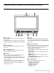
Location and Function of Parts and Controls Front Panel a Tally lamp You can check the status of the monitor by the color of the tally lamp. The tally lamp lights in red, green or amber according to the setting of PARALLEL REMOTE in the REMOTE menu. b Protection plate You can detach the protection plate by removing the four screws. c i (headphones) jack The audio signal which is selected by the input select button is output in stereo sound.
F5 button: H/V DELAY F6 button: VOLUME F7 button: I/P MODE You can assign various functions in FUNCTION BUTTON SETTING of the USER CONFIG menu. Press the button BRIGHTNESS, CONTRAST, CHROMA, VOLUME, PHASE, or APERTURE function assigned to display the adjustment screen. Press the same button again, and the adjustment screen disappears, but you can adjust the value without the setting value display. Using the stand Pull the stand toward you to tilt the monitor screen by 15°.
Input Signals and Adjustable/Setting Items Item Video B&W a a a a Input signal SDI HDMI SD HD 3G SD HD a a a a a a a a a a a a × a a a a a (NTSC) × × × × × × COLOR SPACE a a a a a a a a a a a a a a a a a a a a a AUTO CHROMA/PHASE a ACC a CTI a × × × × × × a a a a a × × × × × × × V SHARPNESS × × × × a × × × × (NTSC) (480/60I) × × × × × SCAN a a a a a a a ASPECT a a a × × a × MARKER a a a a a a a BLUE ONLY a a a a a a
Rear/Bottom Panel a SDI (3G/HD/SD) input and output connectors (BNC) 1 (input) connector, 2 (input) connector Input connector for serial digital component signals. SDI 1 and SDI 2 inputs are available. OUT connector Output connector for serial digital component signals. Note • The signal from the OUT connector does not satisfy the ON-LINE signal specifications. • Output is only activated when the power is on. No output in standby mode.
CAUTION • For safety, do not connect the connector for peripheral device wiring that might have excessive voltage to this port. Follow the instructions for this port. • When you connect the LAN cable of the unit to peripheral device, use a shielded-type cable to prevent malfunction due to radiation noise. • The connection speed may be affected by the network system. This unit does not guarantee the communication speed or quality of 10BASE-T/ 100BASE-TX.
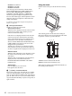
Installing the Arm Mount Bracket Installing to the Rack (Using MB-531) You can install the supplied arm mount bracket, using the supplied four screws. You can attach up to two monitors to the rack by using the optional MB-531 Mounting Bracket. Arm mount bracket 1 Attach the mounting bracket to the monitor. For details on attaching the mounting bracket, refer to the Mounting Instructions of the MB-531. 2 Attach the unit to the rack with four screws. Note The screws are not supplied.
Power Supply Connecting the AC Power Cord Attach the AC adaptor to the monitor, and then connect the supplied AC power cord. Attaching the AC Adaptor AC power cord (supplied) Attaching AC plug holder (supplied) Attach the AC plug holder to the AC power cord, and connect it to the AC IN connector so that the cord does not come loose. Removing CAUTION • The AC adaptor can be used only with products specified by the manufacturer.
Selecting the Default Settings When you turn on the unit for the first time after purchasing it, select the area where you intend to use this unit from among the options. The default setting values for each area 3 1 5 1 4 3 Press the 1 (standby) switch. The unit is turned on and the SELECT SETTING screen appears. 2 3 1 North America 1NORTH AMERICA 2LATIN AMERICA ARGENTINA COLOR TEMP NTSC SETUP COLOR SPACE D65 7.
2 If LATIN AMERICA is selected: PAL&PAL-N area L A T I N AMER I CA PA L &PA L - N_ AREA ARGEN T I NA P ARAGUA Y URUGUA Y NTSC&PA L - M AREA OTHER AREA Selecting the Menu Language Argentina Paraguay Uruguay NTSC&PAL-M area Other area You can select one of seven languages (English, French, German, Spanish, Italian, Japanese, Chinese) for displaying the menu and other on-screen displays. “ENGLISH (English)” is selected in the default setting.
The setting items (icons) in the selected menu are displayed in yellow. Using the Menu USER CONFIG – SYSTEM SETTING NTSC SETUP: F O R M AT D I S P L AY: L A N G UAG E : P O W E R S AV I N G : I/P MODE: LED BRIGHTNESS: RGB RANGE: SD PIXEL MAPPING: xxxxxx xxxxxx ENGLISH xxxxxx xxxxxxx xxxxxx xxxxxx xxxxxxx The unit is equipped with an on-screen menu for making various adjustments and settings such as picture control, input setting, set setting change, etc.
The menu icon presently selected is shown in yellow and setting items are displayed. USER CONFIG – SYSTEM SETTING NTSC SETUP: F O R M AT D I S P L AY: L A N G UAG E : P O W E R S AV I N G : I/P MODE: LED BRIGHTNESS: RGB RANGE: SD PIXEL MAPPING: 3 xxxxxx xxxxxx ENGLISH xxxxxx xxxxxxx xxxxxx xxxxxx xxxxxxx The menu disappears automatically if a button is not pressed for one minute. About the memory of the settings The settings are automatically stored in the monitor memory. Select an item.
Adjustment Using the Menus Items The screen menu of this monitor consists of the following items. STATUS (the items indicate the current settings.
Adjusting and Changing the Settings STATUS menu The STATUS menu is used to display the current status of the unit. The following items are displayed: Submenu Setting COLOR TEMP Selects the color temperature from among D65, D93 and USER setting. MANUAL ADJUSTMENT If you set the COLOR TEMP to USER setting, the item displayed is changed from black to white, which means you can adjust the color temperature. The set values are memorized. • ADJUST GAIN: Adjusts the color balance (GAIN).
Submenu USER CONTROL 1/3 SUB CONTROL CONTRAST: BRIGHTNESS: CHROMA: PHASE: APERTURE: BACKLIGHT: VO L U M E : x x x x x x x Adjusts color intensity (CHROMA) and tones (PHASE). • AUTO ADJ VALUE: Selects ON or OFF of the auto adjustment. When you set to OFF, this parameter is reset to the factory setting. When you set to ON, the automatically adjusted value is enabled.
USER CONFIG menu The USER CONFIG menu is used for setting the system, marker, T/C display, WFM/ALM/VECTOR, focus, function button, closed caption, and audio.
Submenu Setting Submenu Setting SD PIXEL MAPPING Selects SD picture size (pixels) according to the input signal format from the COMPOSITE IN connector. When picture signals in the size of 720 × 576 (50i) (or 720 × 487 (60i)) are input Select 720 × 576 (or 720 × 487). This is the default setting. When 702 × 576 (or 712 × 483) is selected, all sides of the input picture are cut off by several pixels.
IMD (in-monitor display) SETTING Submenu Setting The monitor supports “TSL UMD Protocol - V5.00” provided by Television System LTD. Tally 1 and tally 2 lamp colors, text colors and text display brightness can be set in the setting menu. TEXT COLOR Selects the color of text displayed in IMD. Selecting “0 (commanded color)” sets the same color as set in TSL command. Selecting from 1 and 8 sets the following colors, regardless of the command setting.
WFM/ALM/VECTOR (waveform monitor, audio level meter, and vectorscope) SETTING Submenu Setting When WFM is selected Waveform USER CONFIG – WFM/ALM/VECTOR SETTING 1/2 D I S P L AY: W F M / A L M / V E C TO R : POSITION: T R A N S PA R E N C Y: COLOR: I N T E N S I T Y: ZOOM: LINE SELECT: LINE POSITION: xxx xxxxxx x xxxxx xx x xxx xxx xxx 109% Audio level (dB) OVER 0 100% -10 -20 50% -30 USER CONFIG – WFM/ALM/VECTOR SETTING 2/2 xxx TA R G E T : 0% -4% -60 1 2 Channel number (The channel number w
Submenu Setting When VECTOR is selected Red Magenta Audio level (dB) OVER 0 Submenu Setting TARGET Select 75 or 100. Switches the vectorscope target between 75% and 100%. FOCUS SETTING Bar I -10 Yellow -20 Bar Q -30 Black USER CONFIG – FOCUS SETTING xxx xx x x x FOCUS MODE: COLOR: F R E Q U E N C Y: RANGE: GAIN: -60 1 Green Cyan 2 Blue Color target frame Submenu Setting FOCUS MODE Switches the focus mode. • STD: An image with sharpened edges is displayed.
Submenu Setting F1 BUTTON to F7 BUTTON Assigns the function to the function buttons of the front panel and turns the function on or off. You can assign the function from among SCAN, ASPECT, BLUE ONLY, MONO, MARKER, I/P MODE, etc. Factory setting • F1 button: BRIGHTNESS • F2 button: CONTRAST • F3 button: CHROMA • F4 button: SCAN • F5 button: H/V DELAY • F6 button: VOLUME • F7 button: I/P MODE About the function assigned to the function button SCAN Press the button to change the scan size of the picture.
FOCUS Press the button to confirm the camera focus. An image with sharpened edges is displayed. NATIVE (720p) APERTURE Press the button to adjust the picture sharpness. Press the button to display the adjustment screen and adjust the picture sharpness. Press again to hide the adjustment screen. However, the picture sharpness remains adjustable. Turn the menu selection control right to make the picture sharper and turn left to make the picture softer.
Submenu TYPE Setting Sets the closed caption display type. • AUTO1: Select this to display automatically 608(VBI)*3 when SD-SDI signal is input, or to display automatically 708*1 when HD-SDI signal is input. • AUTO2: Select this to display automatically 608(VBI)*3 when SD-SDI signal is input, or to display automatically 608(708)*2 when HD-SDI signal is input. • 708: Select this to display 708*1 when HD-SDI signal is input. • 608(708): Select this to display 608(708)*2 when HD-SDI signal is input.
Submenu Submenu Setting PARALLEL REMOTE Selects the PARALLEL REMOTE connector pins for which you want to change the function. You can assign various functions to 1 to 4 pins and 6 to 8 pins. The following lists the functions you can assign to the pins. • – – – (“– – –”: No function is assigned.) • COMPOSITE • HDMI • SDI 1 • SDI 2 • WFM/ALM/VS • OVERSCAN • NORMAL • NATIVE • 4:3 • 16:9 • TALLY R • TALLY G • BLUE ONLY • MONO • H/V DELAY • 16:9 MARKER • 15:9 MARKER • 14:9 MARKER • 13:9 MARKER • 1.
Submenu CONNECTION Setting Sets the connection of the monitor and the controller. PEER TO PEER: for one to one connection LAN: for connection via a network KEY INHIBIT menu KEY INHIBIT KEY INHIBIT: xx You can lock the setting so that they cannot be changed by an unauthorized user. Select OFF or ON. If you set to ON, all items are displayed in black, indicating the items are locked.
Specifications Picture performance Panel a-Si TFT Active Matrix LCD Picture size (diagonal) 228.0 mm (9 inches) Effective picture size (H × V) 198.7 × 111.8 mm (7 7/8 × 4 1/2 inches) Resolution (H × V) 1920 × 1080 pixels Aspect 16:9 Pixel efficiency 99.
Available signal formats Note Always verify that the unit is operating properly before use. SONY WILL NOT BE LIABLE FOR DAMAGES OF ANY KIND INCLUDING, BUT NOT LIMITED TO, COMPENSATION OR REIMBURSEMENT ON ACCOUNT OF THE LOSS OF PRESENT OR PROSPECTIVE PROFITS DUE TO FAILURE OF THIS UNIT, EITHER DURING THE WARRANTY PERIOD OR AFTER EXPIRATION OF THE WARRANTY, OR FOR ANY OTHER REASON WHATSOEVER. The unit is applicable to the following signal formats.
Top Dimensions 27 (1 1/8) 100 (4) Front 183.5 (7 1/4) 17.5 (23/32) 166 (6 5/8) 222.4 (8 7/8) Side (When setting the stand using positions B and C for the mounting screws) 38 (1 1/2) Side 161.8 (6 3/8) 148.8 (5 7/8) 130 (5 1/8) 70 (2 7/8) 60 (2 3/8) 5.6 (1/4) 149.6 (6) 13 (17/32) 161.5 (6 3/8) Mass: Approx. 2.0 kg (4 lb 6.5 oz) Approx. 2.
Sony Corporation