
Datasheet


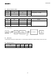


Table Of Contents
- Description
- Features
- Contents
- Package
- Structure
- Block Diagram
- Description of Functions
- Description of Operation
- Recommended operating conditions
- Absolute Maximum Ratings
- Temperature Condition
- Power Consumption
- Clocks
- Electrical Characteristics
- Serial peripheral interface (SPI)
- Quad SPI Flash Interface
- Inter-integrated circuit interface (I2C)
- Universal Asynchronous Receiver Transmitter (UART)
- Inter-integrated sound (I2S)
- Image Sensor Interface
- SD Host Interface
- eMMC Interface
- Universal serial bus (USB) Device
- RTC Signals
- Rise Edge Detection Mode
- Fall Edge Detection Mode
- ADC Analog Input Interface
- Serial wire debug (SWD)
- Notes on Handling
- Pin Configuration
- Pin Description
- Power Pins
- Ball Map
- Power On/Off sequence
- Application Circuits.
- Notice

CXD5602GG
14
− Two dimension Infinite impulse response (IIR) filter
− Norm (Fast Approximate Distance Functions):
− Threshold decision for norm data
Generating interrupt cause
Time-stamp
− Generating time-stamp based-on RTC in PMU to add to sensory data
Sensory Data FIFO
− 40K-Byte with 27
partitions
Decimation data FIFO: 2
External sensor data FIFO: 8
Virtual sensor data FIFO: 10
Host-CPU communication buffer: 1
SPI Interface(SPI3)
− PrimeCell® SSP (PL022)
− Master mode only
− 3 slave select
− Up to 6.5Mbps
Two I2C Bus Interfaces(I2C0, I2C1)
− Multimaster mode only
− Standard-mode(100 kbps)
− Fast-mode(400 kbps)
PWM
PWM counter trigger timing can be connected to the ADC input clock to allow the application to synchronize
PWM and A/D conversion.
− Up to Four PWMs
− Application: vibrator, beeper, LED
A/D Conversions
− 10-bit Low Power (LP)ADC
Up to 4 external channels
4 channels multiplexed mode sampling rate: 256Hz
1 channel mode sampling rate: 32kHz
Application: temperature, etc.
− Two 10-bit High Performance (HP) ADCs
Up to 2MHz
Post decimation filter: Up to 32kHz
Application: vibrator, voice, etc.
Host Interface
The key features:
UART Interface(UART0)