4-174-237-14 (1) Network Camera User’s Guide Software Version 1.2 Before operating the unit, please read this manual thoroughly and retain it for future reference.
Table of Contents Overview Features .................................................................. 4 How to Use This User’s Guide .............................. 5 System Requirements ............................................ 5 Controlling Alarm out 1, 2 ...............................27 Controlling the Day/Night function ..................27 Playing an audio file stored in the camera ........27 Switching TCP/UDP Transmission Mode ..........27 Using the System Utility ................................
CA certificate Tab ............................................ 65 Setting the 802.1X authentication function — Example of Windows Server 2003 ............ 65 Setting the User — User Menu ........................... 68 Setting the Security — Security Menu .............. 69 Saving the Camera Position and Action — Preset position Menu ...................................... 70 Position Tab — Saving pan/tilt/zoom position ...........................................................
Overview Overview Features • High-quality Full HD (1080P) real-time monitoring, up to 30 fps. (SNC-CH240/DH240/CH280/DH280) • High-quality HD (720P) live images from camera can be monitored at a maximum frame rate of 30 fps. • High quality real-time streaming, up to image size 1920 × 1440. (SNC-CH240/DH240/CH280/DH280) • Live images can be streamed in high-quality with maximum SXGA (1280 × 1024) image size. • Exmor CMOS sensor enables high-quality images for streaming.
How to Use This User’s Guide Jumping to a related page When you read the User’s Guide on the computer display, you can click on a sentence to jump to a related page. The following computer environment is necessary for the computer to display images and the controls of the camera. (Aug. 2010) Overview This User’s Guide explains how to operate the Network Camera from a computer. The User’s Guide is designed to be read on the computer display.
Preparation The Preparation section explains what the administrator has to prepare for monitoring images after installation and connection of the camera. Assigning an IP address using SNC toolbox 1 Preparation Assigning the IP Address to the Camera To connect the camera to a network, you need to assign a new IP address to the camera when you install it for the first time.
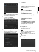
9 Set the IP address. To obtain the IP address automatically from a DHCP server: Select Obtain an IP address automatically. The IP address, Subnet mask and Default gateway are assigned automatically. Note Tip The factory setting of the camera network is DHCP mode for both LAN and Wireless LAN. 7 Select a camera you want to assign an IP address from the list and click Network. The account settings screen is displayed.
The viewer screen of the network camera is displayed on the Web browser. If the message “File Download – Security Warning” appears, click Run. Display sample Program name Preparation Note Note If the IP address is not set correctly, the viewer does not appear after step 13. In that case, try to set the IP address again.
If the information bar appears, click on the bar and select Install ActiveX Control…. 3 Select Off in the Windows Firewall dialog. If “ Internet Explorer – Security Warning” appears, click Install. Preparation Program name The installation of ActiveX Control starts. When installation is completed, the main viewer or the Motion detection menu appears. When accessing with Windows Vista or Windows 7 in SSL communications ActiveX control may not function properly.
6 In the Add Program dialog, select SNC toolbox and click OK. If the pop-up “AutoPlay” appears when a CD-ROM is inserted into the CD-ROM drive, click Install or run program. SNC toolbox is added to the Programs and Services list. 7 Click OK. Preparation Program name Note If you click Open folder to view files, the Web browser will not open automatically. In this case, double-click the “index.htm” file in the CD-ROM. If the message “Internet Explorer” appears, click Yes.
If the message “User Account Control – Windows needs your permission to continue” appears, click Continue. Note If you select Save in the “File Download – Security Warning” dialog, you will not be able to perform installation correctly. Delete the downloaded file, and click the Setup icon again. If “Internet Explorer – Security Warning” appears, click Install. If the message “Internet Explorer – Security Warning” appears, click Run.
4 Select Off in the General tab. 8 Click OK. Preparation The cameras will be displayed in the list. If you want to keep Windows Firewall On, continue with the following steps. 5 Select the Exceptions tab. 6 Click Add Program…. 7 If the Add Program dialog appears, select SNC toolbox and click OK. When the above procedure is completed, the cameras connected in the local network are displayed in SNC toolbox.
Note If you click Open folder to view files, the Web browser will not open automatically. In this case, double-click the “index.htm” file in the CD-ROM. If the message “Internet Explorer” appears, click Yes. Installing ActiveX Control During installation of ActiveX Control, the information bar or “Security Warning” may appear. In this case, operate as follows: If the information bar appears, click on the bar and select Install This Add-on for All Users on This Computer....
4 Select Disable Windows Firewall. Select Allow another program.... 5 Add program. Preparation 4 The cameras will be displayed in the list. To turn Windows Firewall on 1 Select Control Panel from the Start menu of Windows. 2 Click Windows Firewall. 3 Select Allow a program or feature through Windows Firewall. When the above procedure is completed, the cameras connected in the local network are displayed in SNC toolbox.
Accessing the Camera Using the Web Browser The viewer window is displayed (in SSL communication). After the IP address has been assigned to the camera, check that you can actually access the camera using the Web browser installed on your computer. Use Internet Explorer as a Web browser. Start the Web browser on the computer and type the IP address of the camera in the URL address bar. Preparation 1 The viewer window is displayed.
When the viewer of the camera is displayed for the first time When using antivirus software, etc., on the computer “Security Warning” is displayed. When you click Yes, ActiveX control is installed and the viewer is displayed. • When you use antivirus software, security software, personal firewall or pop-up blocker on your computer, the camera performance may be reduced, for example, the frame rate for displaying the image may be lower.
Basic Configuration by the Administrator Preparation You can monitor the camera image by logging in with the initial conditions set for this network camera. You can also set various functions according to the installing position, network conditions or purpose of the camera. We recommend you configure the following items before monitoring images from the camera. Setting contents Setting menu Set the format of the image sent from the camera.
Operating the Camera Administrator and User This network camera identifies those who log in as the Administrator or User. The Administrator can use all the functions of this network camera, including camera settings. The User can use the functions for monitoring the image and audio from the camera, and control the camera. The Viewer mode setting is used to restrict the user’s access rights. There are five types of users.
Logging in to System Logging in as a user 1 Start the Web browser on your computer and type the IP address of the camera you want to monitor. The viewer is displayed. Display sample: Plug-in free viewer This viewer allows the user to select from three image display methods: JPEG, JPEG/FLASH or ActiveX viewer. JPEG method: JPEG images will be displayed in sequence. JPEG/FLASH method: JPEG images will be displayed in sequence. Adobe Flash is required to display the image.
Configuration of Main Viewer Control panel section This section explains the functions of the parts and controls of the main viewer. For a detailed explanation on each part or control, see the specified pages. You can drag the panels to the monitor screen and configure them. To return to the operation panel, drag the panel and configure the operation panel. Click the to hide the detail setting menu or click it again to show the menu.
(Capture) Click to capture a still image shot by the camera and to store it in the computer. Click to open the folder to be saved. Camera control panel Note In the case of Windows VISTA or Windows 7, if “Enable Protected Mode” is checked in Control Panel-Internet Option-Security, still images cannot be shot. (Run)/ (Stop Save Video) Runs and stops Save Video. Click to open the folder to be saved.
Trigger panel Select the Preset position name from the list. The camera will move to the preset position that you have stored in memory using the Preset position menu. Others panel (The Other panel is displayed in the case of an MPEG4 or H.264 image.) Operating the Camera The above is displayed only when Viewer mode (page 69) is set to Full, and one or more triggers are enabled in the Trigger menu (page 88). You can switch between TCP and UDP (Unicast/ Multicast).
Plug-in free viewer Control bar The following operation buttons are available. Main viewer using Plug-in free viewer Display sample: Setting You can set the streaming method, image size, frame rate, PTZ operation mode, trigger selection and image codec. Streaming start button Starts streaming. (Appears while stops streaming.) Streaming stop button Stops streaming. (Appears while streaming.
The available functions for the camera operation modes vary according to the viewer display. The available functions are as follows: Plug-in free viewer ActiveX viewer JPEG JPEG/ FLASH ActiveX Operation from control panel a × × × Area zoom a a a a Vector dragging a a a a PTZ control bar × a a × Pan/Tilt control Click the arrow button in the direction in which you want to move the camera. Keep it pressed to move the camera continuously. To return to the home position, click .
Panning and tilting by dragging the screen (Vector dragging mode only) Using pan/tilt/zoom operations with the displayed control bar (PTZ Control bar only) When you click on the starting point on the image and drag to the end point, the camera pans/tilts in the direction of the arrow from the starting point to the end point. The speed of operation is determined by the length of arrow. Releasing the button on the mouse stops the panning/tilting of the camera.
The current specified position appears on the monitor screen. Using the Trigger Button You can execute various functions by clicking their respective buttons on the Trigger panel. Sending a monitor image via e-mail You can send a captured still image by attaching it to an e-mail. To use this function, you need to make e-Mail (SMTP) active and set the address in the Trigger menu of the Administrator menu properly (page 88). 1 Operating the Camera Click e-Mail (SMTP) on the Trigger panel.
Controlling Alarm out 1, 2 You can control Alarm out 1, 2. To use this function, you need to make Alarm out 1 or Alarm out 2 active in the Trigger menu of the Administrator menu (page 89). 1 Click Alarm out 1 or Alarm out 2 on the Trigger panel. The alarm output is switched by clicking. The alarm output mode can be selected from Toggle or Timer of Alarm out 1, 2 in the Trigger menu (page 89). Tip Controlling the Day/Night function You can set the Day/Night function to On (night mode) and Off (day mode).
Multicast: This protocol is selectable when Multicast streaming (page 48) is On. When Multicast is selected as the transmission port, RTP (Real-time Transport Protocol) and UDP multicast techniques are adopted for video/audio transmission. By selecting it, the network transmission load of the camera can be reduced. If a router that does not correspond to a multicast or firewall is installed between the camera and the computer, video/audio may not play back properly. In this case, select TCP or Unicast.
Connection tab Tip The operation mode of Solid PTZ have been changed for this device. Audio tab Operating the Camera You can set the connection method. Select the start-up connection from: TCP, Unicast, and Multicast. If TCP connection is selected, you can configure proxy settings by selecting Use proxy. View tab Volume Muting: Select this option for Muting the sound at start-up. Use the slide bar to set the volume for start-up sound output.
Note When using the operating system of Windows VISTA or Windows 7, you can not save video if “Enable Protected Mode” is checked in the Control Panel-Internet OptionSecurity. Using the SNC desktop viewer When installation is finished, SNC desktop viewer is displayed on the side bar of Windows Vista or Desktop in the case of Windows 7. Joystick tab Operating the Camera You can assign the joystick buttons here.
How to control PTZ Select the PTZ operation mode for the Gadget screen from the options Area zoom, PTZ control bar, and Vector dragging. Operating the Camera Click (Exit) to exit Gadget. When you click (Set), you will see the following setting screen. Tip The operation mode of Solid PTZ has been changed for this device.
Administrating the Camera 3 Example: “System” menu This section explains how to set the functions of the camera by the Administrator. For details about monitoring the camera image, see “Operating the Camera” on page 18. This section explains the basic operations and each option of the Administrator menu. Click the menu name (example: System) on the left side of the Administrator menu. The clicked menu appears. 4 Select the required tab above the menu, and set each setting option in the tab.
Configuration of the Administrator menu Camera Position and Action — Preset position Menu” on page 70) e-Mail (SMTP) Displays the e-Mail (SMTP) menu for sending an email. (“Sending an Image via E-mail — e-Mail (SMTP) Menu” on page 73) FTP client Displays the FTP client menu for sending an image/ audio file, etc., to an FTP server. (“Sending Images to FTP Server — FTP client Menu” on page 76) Image memory Displays the Image memory menu for recording an image/audio file, etc.
Alarm buffer Displays the Alarm buffer menu for the buffer for storing the image and audio related to alarm detection. (“Setting the Alarm Buffer — Alarm buffer Menu” on page 90) Configuring the System — System Menu Event detection Displays the setting menu for all built-in detection functions. (“Setting the Sensor input/Camera tampering detection/Motion detection/Audio detection — Event detection Menu” on page 91) When you click System in the Administrator menu, the System menu appears.
Maximum wait number Sets the number of users who are permitted to wait for their turn for control authority during operation by one user. The selectable number is from 0 to 10. This is effective when Exclusive control mode is set to On. Date & time Tab Notes • To use Exclusive control mode, the date and time of the camera and the connected computer must be set correctly first. • To use Exclusive control mode, do not disable the Web browser Cookie. If it is disabled, this mode cannot be used.
NTP server 3: Enter the third choice for NTP server address. DHCP server: Select DHCP server when you need to get NTP server information from DHCP server. Multicast: Select Multicast when you search for an NTP server with Multicast. Font size Set the font size. Style Set the items to superimpose and the format to display in. Superimpose settings are available for the following items: Time zone • Date: Set the display settings for date and time.
Superimpose format Click Edit to edit the content to superimpose over each display position. Only one Date and one Camera ID can be specified for the Superimpose format. You can set the content to superimpose in the “Lower left”, “Lower right”, “Upper left”, “Upper right”, “Center”, “Top” and “Bottom” parts, respectively. However, if you specify the “Top”, superimposed content will not appear on the upper left or upper right.
OK/Cancel See “Buttons common to every menu” on page 32. The file name preset at the factory is “snc-ch140.cfg” for SNC-CH140. Restore setting Initialize Tab Loads the stored setting data of the camera. Click Browse and select the file in which the setting data is stored. Click OK, and the camera is adjusted according to the loaded data, and restarted.
Capture full image When you click Capture, a full image covering the entire shooting range is shot and saved to the camera. The full image is captured regardless of the image size and crop settings. System log Tab Note Main viewer image may be interrupted or image and/or audio files may not be created correctly during image capturing. Delete image By pressing Delete, you can delete the full image recorded in the camera.
Setting the Camera Image and Audio — Camera Menu Codec Select the bit rate of audio from the m microphone input connector. G.711 (64kbps), G.726 (40kbps), G.726 (32kbps), G.726 (24kbps) or G.726 (16kbps) can be selected. Note When you click Camera in the Administrator menu, the Camera menu appears. Use this menu to set the functions of the camera. The camera menu consists of the following 7 tabs. SNC-CH240/CH140: Common, Focus, Picture, Privacy masking, Day/Night, Video codec, and Streaming.
Preview screen Preview the image and adjust the focus. The current image focus position is superimposed when adjusting the focus. For the details on each button, refer to the Control bar of the Plug-in free viewer (page 23). Note If you click the buttons in this tab, in order to adjust the focus easily, the settings below are temporarily changed: – Privacy masking and Cropping are deactivated. – The current image focus position is superimposed. – The alarm of Motion detection is deactivated.
Preview screen Preview the image and adjust the picture setting. For details on each button, refer to the Control bar of the Plug-in free viewer (page 23). Note This cannot be selected when Visibility Enhancer is On. Auto iris View-DR In high-contrast scenes such as against a back light, this function reduces overexposure and underexposure. Select On to turn on the View-DR function. Notes • When the View-DR function is on, exposure-related settings cannot be configured.
When Off is selected, the automatic exposure function cannot be set in the long term exposure mode. Note When View-DR is On, ATW-PRO cannot be selected. Notes • This cannot be selected when View-DR is On. • If the shutter speed is Fixed 1, 1/2, 1/4, 1/8 or 1/15, this setting will be fixed to Off. Tip Depending on the setting, the range of Auto-controlled shutter speed is as follows Shutter speed: Fixed • When Auto slow shutter is Off Shutter speed is fixed to the value set in Shutter speed.
Control buttons The control buttons are located at the top of the preview screen. You can operate the camera with these buttons. Day/Night Tab Use this tab to set the day/night function of the camera. Pan/Tilt operation Click the button of the direction you wish to move the camera. Zoom operation Available by clicking – to zoom out and + to zoom in. Position Available to call out the privacy masks, delete them one by one or delete all at one time.
Click Schedule to display the setting menu for the effective period. (“Setting the Schedule — Schedule Menu” on page 90) Video codec Tab Use this tab to set the items for the video codec. Sensor input: Controls the day/night mode by synchronizing it with the sensor input. While a sensor input is detected, the camera works in night mode.
3 4 Click OK at the bottom of the window. The cropped image is displayed on the main viewer. To close the image, click corner. in the upper-right Note Solid PTZ is not available when cropping is set to On. Image 1 and Image 2 Up to two image codec modes can be set. Configure the following setting for each image mode. Codec Select JPEG, MPEG4, H.264 or Off. Note that Image 1 cannot be set to Off.
Maximum image size [1920 × 1440] Image 1 Image 2 1920 × 1440 a × 1600 × 1200 a × 1680 × 1056 a × 1920 × 1080 a × 1440 × 912 a × 1376 × 768 a × SNC-CH140/DH140/CH180/DH180/DH140T Image size [1280 × 1024] Image 1 Single codec Image 2 Codec Frame rate (fps) Codec H.264 20 - MPEG-4 25 - Frame rate (fps) JPEG 30 - 15 H.264 6 1280 × 1024 a × H.264 1280 × 960 a × H.264 15 JPEG 10 1280 × 800 a × H.
Bit rate Set the bit rate of MPEG4 or H.264 image transmission for a line. When the bit rate is set to a high level, better image quality can be enjoyed. Selectable bit rates are as follows: 64, 128, 256, 384, 512, 768, 1024, 1536, 2048, 3072, 4096, 5120, 6144, 7168, 8192 (kbps) I-picture interval Set the I-picture insertion interval.
Audio port number Specify the audio transmission port number used for the multicast streaming. It is initially set to 60002. Specify an even number from 1024 to 65534. Two port numbers (the number specified here and an odd number with 1 added to the specified number) are used for audio data communication and control. Configuring the Network — Network Menu Specify different numbers for the video port number and the audio port number.
Obtain an IP address automatically (DHCP): Select this option when a DHCP server is installed on the network to allow IP address assignment. With this setting, the IP address is assigned automatically. Use the following IP address: Select this option when you set a fixed IP address. With this setting, specify the IP address, Subnet mask and Default gateway manually. Note When you select Obtain an IP address automatically (DHCP), make sure that a DHCP server is operating on the network.
Wireless Tab — Setting of wireless connection (SNC-CH240/CH140/ CH180/CH280 only) Insert the specified wireless card into the CF card slot of the camera, and set the items for connecting to the wireless network. Before setting, read the operation manual and installation manual supplied with the wireless card together with this guide. MAC address Displays the MAC address of the wireless card inserted in to the CF card slot. If a wireless card is not inserted, “00:00:00:00:00:00” will be displayed.
Secondary DNS server Type the IP address of the secondary DNS server, if necessary. MTU Enter the MTU value for wireless network. (1000 -1500) If IPv6 is enabled, the value must be 1280 or greater. Host name Type the wireless network host name of the camera to be transmitted to the DHCP server. This setting is valid only when Obtain an IP address automatically (DHCP) is selected in the Wireless tab. Domain suffix Type the wireless network domain suffix of the camera to be transmitted to the DHCP server.
WEP Set up this item when WEP is selected on Security. Use WEP key automatically generated Checking this box allows you to use an automatically generated WEP key. Uncheck the box when you enter a WEP key manually. To use the automatically generated WEP key, you need to enable the 802.1X (wireless) function. After checking this box, click OK at the bottom of the window. The 802.1X function is enabled. Note For correct operation of the 802.1X function, you need to configure the 802.
QoS Tab Protocol Select the protocol. In this tab, you can mark the data traffic packets sent from the device and configure the settings for QoS control. Rules for the types of data traffic can be created using IPv4/IPv6 address, port number, protocol, etc. A maximum of 10 rules can be registered for IPv4 and IPv6, respectively. DSCP Set a value to mark the data traffic (0 ~ 63). This value is set in the DSCP field included in the IP header of the data traffic. Set Used when registering on the QoS table.
Prefix Enter the prefix value of the target on which to perform QoS. Tip The prefix value represents the number of bits from the left side of the network address. Port Enter the port number for the data traffic of the device (e.g. HTTP:80). OK/Cancel See “Buttons common to every menu” on page 32.
Note Note The model on sale in China does not support the STARTTLS function. The model on sale in China does not support the CRAM-MD5 authentication. Authentication User name, Password Type the user name and password of the owner of the mail account, using up to 64 characters. This setting is necessary when the SMTP server that sends e-mails performs authentication. Select the authentication required when you send an e-mail. Off: Select if no authentication is required when an e-mail is sent.
parameter: Type the command parameter if necessary. You can use the special tags mentioned below for the parameters. Proxy server name When you send an HTTP request via a proxy server, type the name or IP address of the proxy server, using up to 64 characters. Proxy port number Specify the port number when you send an HTTP request via the proxy server. Set a port number between 1024 and 65535. Setting the SSL function — SSL Menu When you click SSL in the Administrator menu, the SSL menu appears.
When you use SSL connection for the first time When you use SSL connection only with the SSL function On, you cannot access the camera if the SSL function does not work properly. In this case, you must reset the camera to the factory settings. (All settings will be initialized.) To avoid this, check that SSL connection is possible by performing the following steps. 1 Set the SSL function to On, and select Allow HTTP connection for some clients. 2 Click OK to close the main viewer and the setting window.
To display certificate information When the certificate has been set in the camera correctly, its information appears on Status, Issuer DN, Subject DN, Validity Period and Extended Key Usage. Status Shows if the status of the certificate is valid or invalid. The following statuses are recognised. Click Cancel at the bottom of the menu if you want to cancel changing the private key password after clicking Reset.
To import the CA certificate How to install the CA certificate 1 Click Browse… to select the CA certificate to be saved in the camera. 2 Click Submit The selected file will be imported to the camera. The camera may not be connected because the browser (Internet Explorer) does not display whether the certificate will be accepted or not due to the type of certificate. In this case, install the CA certificate as follows.
3 4 To remove an installed CA certificate 1 In Internet Explorer, click in the order Tools, Internet options, Content tab and Certificates. The Certificates dialog appears. 2 Select the certificate you want to remove. The CA certificate is usually stored in Trusted Root Certification Authorities. 3 Click Remove. Do you want to delete the certificate appears to confirm. 4 Click Yes. The certificate will be removed.
4 Select Certificates from the list, then click Add. Certificate Snap-in is displayed. 5 Select Computer account as the certificate administrated in this Snap-in, then click Next. 6 Select Local Computer as the computer administrated in this Snap-in, then click Finish. 7 Close Add Standalone Snap-in (for Windows XP Professional only) and Add/Remove Snap-in... dialogs. The items for administrating Certificates appears in the Console Route window. Confirm the relevant certificate, then remove it.
Supplicant A supplicant is a device that connects to the authentication server to join the network. This camera serves as a supplicant in the 802.1X network. The supplicant can enter the 802.1X network after appropriate authentication by the authentication server. Authenticator An authenticator forwards certificate request data or response data that the supplicant or authentication server issues to the other party. Normally a hub, router or access point serves as an authenticator.
Client certificate Tab When TLS is selected as the EAP method, client certificate is imported for authentication at the camera. Client certificate request Note When the client certificate to be imported is of PKCS#12 format and the private key password is not set correctly, “” is displayed in the boxes of Issuer DN, Subject DN, Validity Period and Extended Key Usage. Specify the correct private key password to confirm the information of the certificate.
CA certificate Tab You can import a trusted CA certificate (server certificate or route certificate) to the camera. Up to four certificates from trusted CAs can be imported to the camera. Only the PEM format is supported. Setting the 802.1X authentication function — Example of Windows Server 2003 This section explains how to configure the authentication server and CA using Microsoft Windows Server 2003.
3 Select New from the context menu, then select Group and configure the group for 802.1X connection. For example, the group “Wired_802.1X_Group” is assumed for explanation purposes. 10 Set the following items: Friendly name: Type “authenticator” as an example. Client address (IP or DNS): IP address of the authenticator Client-Vender: RADIUS Standard Shared secret: Specify the shared secret to be set in the authenticator.
The “Microsoft Certificate Services” page opens. 3 Type the log-in user name and password correctly. The “Microsoft Certificate Services” page opens. 4 Click Request a certificate, advanced certificate request and Create and submit a request to this CA in sequence. 5 Set the following items. Note 3 Certificate Template: User Key Options: Create new key set – CSP: Microsoft Enhanced Cryptographic Provider v1.0 – Key Size: 1024 – Check Mark keys as exportable.
10 Click Next and select as follows. Do you want to export the private key with the certificate?: Select Yes, export the private key. Select the format you want to use: Select Personal Information Exchange – PKCS#12(PFX). Password: Specify the private key password. File to export: Specify the name of the file to be exported. The certificate is exported. Import the exported file to the camera as the camera’s client certificate.
Viewer mode When the user is authenticated for logging in the main viewer, select the viewer mode to be displayed after authentication. Full: The user can operate all functions in this mode. Pan/Tilt: In addition to the Light mode, the user can operate pan/tilt/zoom. Preset position: In addition to the Light mode, the user can perform the camera’s preset position settings. Light: In addition to the View mode, the user can select the image size of the main viewer, select codec and capture a still image.
Saving the Camera Position and Action — Preset position Menu When you click Preset position in the Administrator menu, the Preset position menu appears. This allows you to save the camera’s pan, tilt and zoom positions and set position (programmed action of the camera). The Preset position menu consists of 2 tabs: Position and Preset tour. The Preview screen is displayed. Note Preset position menu is not available when Solid PTZ is set to On in the Camera menu-Video codec tab.
Preset You can configure and save preset positions and thumbnails. Click Call to move the camera to a specified preset position and click Clear thumbnail to delete the thumbnail information for the specified preset position. No. Select a preset number from 1 to 8 from the drop-down list. New Group You can register a new group. Rename You can rename the group and preset positions. Clear You can delete the group and preset positions.
Resume time on inactivity This item becomes active when Tour is set to On. With this item, you can select whether you restart or stop the tour after it has stopped by manual pan, tilt or zoom operation or by camera movement to the preset position triggered by an alarm. On: Specify the wait time before the tour restarts, between 5 and 3600 seconds. The tour restarts automatically after the specified time has elapsed. Off: The tour does not restart. Tour A to Tour E Configure Tour A to Tour E respectively.
Sending an Image via E-mail — e-Mail (SMTP) Menu When you click e-Mail (SMTP) in the Administrator menu, the e-Mail (SMTP) menu appears. Using the e-Mail (SMTP) function, you can send an e-mail with an attached image file that has been shot linked with an external sensor input or with the built-in detection functions. An image file can also be sent periodically. The e-Mail (SMTP) menu consists of three tabs: Common, Alarm sending and Periodical sending.
POP port number Enter a port number from 110 to 65535. The standard port number is 110. If TLS is enabled, the standard port number for POP3s is 995. Alarm sending Tab — Setting the e-mail sending mode when detecting the alarm Authentication mode Select Login or CRAM-MD5 as the authentication method for SMTP authentication. Set to send an e-mail linked with alarm detection by the external sensor input or by the built-in detection functions.
Sequence number: A sequential number of 10 digits between 0000000001 and 4294967295 and two fixed digits 00 are added to the image file name. Sequence number clear Click Clear to reset the Sequence number suffix to 1. Periodical sending Tab — Setting the periodical e-mail sending mode You can set to send e-mails periodically. Alarm Select the alarm to be linked with e-mail notification.
Effective period Set the period during which periodical sending will be effective. Always: Periodical sending is always effective. Schedule: You can specify the period during which periodical sending is effective. Click Schedule and the menu for the effective period is displayed. (“Setting the Schedule — Schedule Menu” on page 90) OK/Cancel See “Buttons common to every menu” on page 32.
Passive mode Set whether you use the passive mode of FTP server or not when connecting to the FTP server. Select On to connect to the FTP server using the passive mode. OK/Cancel Sequence number: A sequential number of 10 digits between 0000000001 and 4294967295 and a sequential 2-digit number are added to the image file name. Tip See “Buttons common to every menu” on page 32.
Note When Edge Storage is enabled, the Alarm buffer is not available. OK/Cancel See “Buttons common to every menu” on page 32. Sequence number: A sequential number of 10 digits between 0000000001 and 4294967295 and two fixed digits 00 are added to the image file name. Sequence number clear Click Clear to reset the Sequence number suffix to 1. Mode Select the periodical sending mode.
Recording Images in Memory Common Tab — Setting the image memory function — Image memory Menu Image memory To use the image memory function, select On. x SNC-CH240/CH140/CH180/CH280 Selected root directory Administrating the Camera When you click Image memory in the Administrator menu, the Image memory menu appears. By using the image memory function, you can record an image and audio file (shot being linked with the external sensor input or built-in detection functions) in the builtin memory (approx.
On: A warning mail is sent to the Administrator. Off: A warning mail is not sent to the Administrator. Note When Overwrite is set to On, a warning mail is not sent to the Administrator. SMTP server name Type the name of the SMTP server for sending an email, using up to 64 characters. Otherwise type the IP address of the SMTP mail server. SMTP port number Enter a port number from 25 to 65535. The standard port number is 25. If TLS is enabled, the standard port number for SMTPs is 465.
Alarm recording Tab — Setting the Image memory function when detecting the alarm You can set to record an image and audio file to the memory linked with an external sensor input or built-in detection functions. Alarm Select the alarm to be linked with the recording of image and audio files. Sensor input 1: The external sensor that is connected to sensor input of the camera I/O port. Camera tampering detection: An alarm that is triggered if the camera detects tampering, such as direction shifting or spray.
Periodical recording Tab — Setting the periodical recording mode You can set to record video files (JPEG files) periodically. Periodical mode: An image file is sent periodically according to the specified Interval and Effective period. Tour mode: An image file is sent each time the camera is moved to a preset position during the tour. Interval Type the interval at which you want to send images to the FTP server periodically.
About the extension of a file A file to be recorded/sent using the image memory function Edge Storage function or the Mail (SMTP)/ FTP client function has one of the following four extensions depending on the video mode setting and the recording/sending settings of the camera. .m4f: MPEG4 image files (including sound) .jpf: JPEG image files (including sound) .jpg: JPEG still image files .maf: H.264 image files (including sound) The SNC video player (page 119) allows playback of “.m4f”, “.maf” and “.
Setting the Edge Storage — Edge Storage Menu (SNC-CH240/CH140/CH180/ CH280 only) • Edge Storage is not available for SNC-CH180/CH280 when powered by PoE. Edge Storage Select On to use Edge Storage. Alarm buffer is not available when On is selected. CF memory card Display the available free space of external CF memory. Note The video or audio data of Edge Storage cannot be recorded in the built-in memory.
Recording time Post-alarm duration Type the recording time of the image/audio after alarm detection. Motion detection: The alarm detected by the motion detection function. Click Detection, and the Motion detection menu is displayed to allow you to set the motion detection function (page 91). Audio detection: The alarm detected by the audio detection function. Click Detection, and the audio detection menu is displayed to allow you to set the audio detection function (page 91).
Setting the Alarm Output — Alarm output Menu When you click Alarm output in the Administrator menu, the Alarm output menu appears. You can perform setting in this menu to control the alarm output of the I/O port on the rear of the camera linked to alarm detection, the timer and the Day/Night function. The Alarm output menu consists of two tabs: Alarm out 1 and Alarm out 2. Tip For details on connection of peripheral devices to the alarm output of the I/O port, refer to the supplied Installation Manual.
Outputting Audio Linked to Alarm Detection — Voice alert Menu Click Voice alert in the Administrator menu to display the Voice alert menu. Use this menu to set the voice alert function to output audio from the line output jack of the camera when an alarm is detected by the sensor input or detection functions. You can output the audio from a speaker connected to the camera in synchronization with an alarm event triggered by the sensor input or the detection functions.
Setting the Operations from the Viewer — Trigger Menu Click Trigger in the Administrator menu to display the Trigger menu. This allows you to select the activities that can be performed when the button on the Trigger panel is clicked on the main viewer. FTP client Checking this box allows you to select FTP client on the Trigger panel in the main viewer. By clicking FTP client a still image of the moment you click is captured, and the image file is sent to the FTP server.
Alarm output 1, 2 Checking this box allows you to select Alarm output 1 or Alarm output 2 on the Trigger panel in the main viewer. You can control the alarm outputput by clicking Alarm output 1 or Alarm output 2. File Displays the name of the audio file saved in the camera. “Not uploaded” is displayed dimly if no audio file is saved. OK/Cancel Select the alarm ouput control mode from Toggle or Timer. Toggle: Each time you run a trigger, On (short circuit) or Off (open) is switched.
Setting the Schedule Setting the Alarm Buffer — Schedule Menu — Alarm buffer Menu When you click Schedule in the Administrator menu, the Schedule menu appears. The Schedule menu consists of 8 tabs. This is the same menu as the Schedule menu that is displayed when you click Schedule to set the Effective period in the following menus. When you click Alarm buffer in the Administrator menu, the Alarm buffer menu appears.
Setting the Sensor input/ Camera tampering detection/Motion detection/Audio detection — Event detection Menu When you click Event detection in the Administrator menu, the Event detection menu appears. The Event detection menu consists of the Sensor input, Camera tampering detection, Motion detection and Audio detection tabs. OK/Cancel See “Buttons common to every menu” on page 32.
Disappearance When a moving object disappears from the designated area, it will set off an alarm. FTP client alarm sending, image memory alarm recording and/or audio file playback can be performed in synchronization with this alarm. Capacity Setting items for motion detection Use the settings tab to set the conditions for the motion detection function while observing camera images.
Add detection area Clicking this button will add an active area window in the center of the screen. When you place the cursor on the area, the cursor changes to a crossed arrow, which you can drag to move the area. When you place the cursor on the vertex of the area, the cursor changes to n, which you can drag to move the vertex. Add non detection area Clicking this button will add an inactive area window in the center of the screen.
Moving shadow exemption Set ON/OFF for the moving shadow exemption function of motion detection. Selecting Do not respond to shadows will prevent the shadows of a moving object from being recognized as moving objects. Remove the check to disable the shadow removal function of motion detection. Filter type Specify the VMF filter type. VMF settings Up to three VMF settings (package number 1 to 3) can be retained for the current camera position. You can select one of those settings for use.
x VMF status indicator of each filter The filter is on when the set filter type conditions (Passing, Existing, Appearance, Disappearance, Capacity) are met. Existing Tip The buttons displayed on the edit screen for filter is used in the same way as those for detection setting. See page 92. Passing Administrating the Camera Similar to a active window an trigger area can also be moved and vertexes can be moved/added or deleted.
Disappearance Trigger size Specify the minimum trigger size and maximum trigger size of the object. To specify the size, you can either enter values or drag the vertexes of the area. Administrating the Camera This criterion is whether an object disappeared in the trigger area. Similar to an active window, a trigger area can also be moved and vertexes can be moved/added or deleted. Capacity The size of an object is measured in pixels.
Trigger speed Specify the range of the speed of object to inspect by determining Min. speed and Max. speed. Audio detection tab — Set the audio detection Audio detection detects sound picked up by a microphone, and outputs an alarm beyond a certain threshold. Audio detection Select On to activate the function and set the sensitivity. Sensitivity Note The set value is only valid under the conditions of Passing, Appearance or Disappearance.
OK/Cancel See “Buttons common to every menu” on page 32. Configuring the Viewer — Viewer Menu Click Viewer in the Administrator menu to display the Viewer menu. Using this menu, you can select the viewer to use and configure advanced settings. Layout tab Administrating the Camera Homepage Set the viewer or homepage to be displayed at the time of access. ActiveX viewer: Displays the ActiveX viewer at time of access.
Plug-in free viewer: Displays the Plug-in free viewer at time of access. Custom: Select the homepage to be displayed. With SNC-CH240/CH140/CH180/CH280, you can write data in the built-in flash memory or CF memory card (not supplied) to use your favorite homepage. With SNC-DH240/DH140/DH180/ DH280, write data to the built-in flash memory to use your favorite homepage. To store a homepage HTML file in the built-in flash memory, use the Custom Homepage function of SNC toolbox included in the supplied CD-ROM.
Registering in Cameras Specify a number on the camera list and set the IP address, port number, and comment for each camera. Insert: Click to register a camera in the camera list. Modify: Click to edit a selected camera list. Delete: Click to delete a selected camera list. Down: Click to decrement the number indicating registered camera numbers. Up: Click to increment the number indicating registered camera numbers.
Show menu Set whether to show or hide operation buttons at the bottom of the camera image area. Select On to display the menu, select Off to hide the menu. When On is selected, the items below can be set: HTML output tab If the monitor is for personal use, this tab can be used to output sample source for HTML and script. For details on the setting, refer to “Monitor” of the Layout tab. Administrating the Camera Streaming: Displays the setting options of Streaming, if it is checked.
Others How to use SNC toolbox Menu bar Function buttons This section explains how to use the application software and commands, including the supplied CDROM. *** Using the SNC toolbox Explains the functions except those of the Network tab in SNC toolbox. To install SNC toolbox, to assign an IP address and to set the network, see “Assigning the IP Address to the Camera” on page 6 in “Preparation”.
Privacy Masking: Displays the Privacy Masking screen. Panorama Creator: Displays the Panorama Creator screen. Not available with this product. Custom Homepage: Displays the Custom Homepage screen. Firmware Upgrade: Displays the Firmware Upgrade screen. Initialize Device: Reboot: Restarts the device. Factory Default: Initializes the device to factory default. Backup setting data: Backs up setting data on a computer. Restore setting: Restore the backup setting data to the device.
Serial No. Displays the serial number. Version No. Displays the version of firmware. Registering by Add Device Entry dialog 1 Select the folder to register the device. 2 Right click the mouse and select Add Device Entry from the displayed menu. The Add Device Entry dialog appears. 3 Enter the following items: Device name: Enter a device name of your choice. Device address: Enter the address of the device to register. HTTP port No.: Normally, 80 should be selected.
Renaming the device/folder Display with large thumbnails Select the folder or device to rename and right click the mouse. Select Rename from the displayed menu. The device/folder name is highlighted. Enter the new name. Select Snapshot(L) from the View menu or click set to display with large thumbnails. to Deleting a device/folder Select the device/folder to be deleted from the Device list or Device tree and right click the mouse.
Setting SNC toolbox options Network tab Select Option from the Tools menu to display the “Option” dialog. This dialog consists of three tabs: General, Network and Log. General tab Others Language Set language. Default device account Set the initial values of user name and password for the administrator accessing the device for each device. Show warning dialog when closing main window: Select to display the warning message. Remind me the risk when assigning IP: Select to display the warning message.
Log tab Privacy Masking screen Overwrite the oldest log file To set the size of the log file, check Enable and specify the minimum required space for a log file. Others Log output folder Click Browse to display the folder selection dialog. Specify the folder to save the log. Using Privacy Masking — Masking a Camera Image The Privacy Masking function of SNC toolbox allows you to mask parts of the camera image to be transmitted. 1 Select the camera to set a privacy mask from the Device list.
Number The set mask number is displayed in the Viewer when Solid PTZ (page 45) is off. Frame When Solid PTZ (page 45) is off. display the frame of the set mask to distinguish the mask area when the set mask is overlapped. Panorama area Display the panorama when Solid PTZ (page 45) is on. The set privacy mask is displayed by numbers on the panorama. When the panorama is clicked, the camera will focus on the place clicked.
Note If you cannot establish communications with the camera using the proxy server being used, connect the camera to the local network and run the Custom Homepage without using the proxy server. *** *** Device list Module list Tip Type the path in which your homepage is stored. 4 Click Start uploading. Uploading of the homepage file to the camera starts. 5 Click Cancel to exit the program.
Displays Task Wizard. Notes • To stop upgrading, click Stop upgrading. To protect some devices, during the process of upgrading, upgrading cannot be canceled. • Do not turn off the power until the device restarts after upgrading. Using the Schedule Task You can specify the time or interval to change the Device setting or perform Firmware upgrade. Click Task to display the Task List, which shows a list of scheduled executable tasks. 2 Click Next. 3 Select a device to which the task is assigned.
Recurrence pattern Specify the operation interval. Onetime: Runs the task once. Hourly: Specify the operation frequency in units of hours. (Possible set value: 1 to 99) Daily: Specify the operation frequency in units of days. (Possible set value: 1 to 99) Weekly: Specify the operation frequency in units of weeks and days of the week. (Possible set value: 1 to 99) Select Device Setting or Firmware Upgrade. 6 Range of recurrence Specify the starting date and time, and the end date and time.
Setting tree All settings are sorted into categories. Click + to display the subcategories under a category. Click – to hide the subcategories. Select a subcategory to display setting items on the right side of the screen. Setting items Pages to refer to in “Administrating the Camera” Device “Setting the Camera Image and Audio — Camera Menu” on page 40 Item Displays the setting items. Select a line to change its value. Value Displays the value of an item. Select or enter a value to change the value.
Setting items Pages to refer to in “Administrating the Camera” Setting items Pages to refer to in “Administrating the Camera” e-Mail (SMTP) “Sending an Image via Email — e-Mail (SMTP) Menu” on page 73 Voice Alert “Outputting Audio Linked to Alarm Detection — Voice alert Menu” on page 87 Common Alarm sending Periodical sending FTP client “Common Tab — Setting the e-Mail (SMTP) Function” on page 73 Voice alert 1 “Alarm sending Tab — Setting the e-mail sending mode when detecting the alarm” on pa
3 Using the SNC audio upload tool — Transmitting Note If you click “Save this program to disk” on the “File Download” dialog, you cannot install the tool correctly. Delete the downloaded file, and click the Setup icon again. Audio to Camera The supplied SNC audio upload tool allows you to transmit sound from the computer to the camera. This section explains the setup and operations of the SNC audio upload tool. 4 The SNC audio upload tool supports the following audio data to be transmitted.
Using the SNC audio upload tool When you start the SNC audio upload tool, the Setting tab is displayed. Setting tab Use this menu to set the camera to transmit audio from a computer or upload an audio file. Proxy port: Type the port number used for communication with the proxy server. Note The Proxy setting is applicable to all cameras. You cannot use individual proxy settings for each camera. Codec Select the audio mode (Codec) from the drop-down list.
Serial: Displays the serial number of the network camera. User: Displays the specified user ID and password. The password is shown as turned letters. Select all Click to select all the cameras in the camera list. This is useful, for example, when you delete all the cameras from the list or specify the same user ID and password for all cameras. UserID/Password Use this item when you specify the user ID and password to communicate with selected camera(s) only.
Notes • Audio transmission stops if you switch the tab during transmission. • Audio may be interrupted when the IP address is changed if Obtain an IP address automatically (DHCP) is set on IP address in the Network menu. • Audio may be interrupted if you transmit it to many cameras simultaneously. Voice alert tab Use this menu to record sound via a microphone connected to the computer, and upload the recorded audio file to the camera.
Recording/playback progress bar Target camera(s) (Camera list) Displays the cameras selected with the camera select checkbox of the camera list in the Setting tab. The list shows information and status of selected cameras. You can check recording or playback progress with this bar. During recording, the far right of the bar represents 30 seconds, and the remaining recording time is numerically displayed below the bar. During playback, the length of the bar depends on the recorded time.
Saving the recorded audio file to the computer 1 Click (recording) in the Voice alert tab to start recording. 2 Click (stop) to stop recording. Recording will stop automatically in 30 seconds. 3 Click (save). The Save as dialog appears. Type the file name and save it. Uploading the saved audio file to the camera 1 Click (file open) in the Voice alert tab and select the audio file to be uploaded. 2 Select the voice alert number. 3 Click camera.
Using the SNC video player 1 Start the SNC video player. Record event: Type of event used for the recording: Sensor input, Camera tampering detection, VMF, Motion detection, Audio detection, Network disconnection. Playing a video/audio file Click (start) to start playback from the beginning of the selected file. To freeze the movie temporarily, click (pause). Click again to resume playback from the freeze point. To stop playback, click (stop). To start playback from the beginning, click (start) again.
Assigning the IP Address to the Camera Using ARP Commands – Do the computer and the camera have the same network address? If not, set the same network address on the computer and the camera. This section explains how to assign an IP address to the camera using ARP (Address Resolution Protocol) commands without using the SNC toolbox. Note When you turn on the camera, execute the ARP and PING commands within 5 minutes. Also when you restart the camera, execute the operation within 5 minutes.
Using the SNMP This unit supports SNMP (Simple Network Management Protocol). You can read MIB-2 objects using software such as SNMP manager software. This unit also supports the coldStart trap which occurs when the power is turned on or the unit restarts, and the Authentication failure trap, which informs of any illegal access using SNMP. Using CGI commands, you can set the community name and access limitation, host to send traps, and some MIB2 objects.
3) sysName= Set the case of “mib-2.system.sysName.0” in the position. The maximum length of is 255 characters. Glossary ActiveX control 4) enaAuthTraps= Set the case value of “mib-2.snmp.snmp EnableAuthenTraps.0” in the position. Type “1” (enable) or “2” (disable) in the position. 5) community=,r, , Set the community attributes.
DHCP server H.264 Acronym for Dynamic Host Configuration Protocol server. The IP address of a terminal without an individual IP address can be automatically distributed by the Dynamic Host Configuration Protocol (DHCP). The DHCP server assigns the IP addresses to the terminals. An image compression format. The standard written by the JVT (Joint Video Team) a joint organization for standardization (composed of ISO and ITU-T. H.
Primary DNS server SNMP One of the DNS servers that can first reply to a request by connected devices or other DNS servers. A protocol for monitoring and managing network devices. Proxy server SSL A server or software that acts as an intermediary between a local network and the Internet so that it can connect to the Internet in place of a computer on a local network. Acronym for Secure Sockets Layer.
Index Numerics 802.1X.............................. 53, 62, 125 A Others Access log ......................................39 Active Directory .............................65 ActiveX control .................... 8, 11, 16 ActiveX viewer......................... 19, 20 Adaptive rate control ......................48 Adjust .............................................35 Administrator ........................... 18, 68 Administrator e-mail address.............................. 56, 74, 80 Administrator menu .
I image file ....................................... 26 Image file name....... 74, 77, 78, 81, 82 Image memory ..............26, 33, 79, 88 Image memory Menu..................... 79 Image quality ................................. 48 Image size ...................................... 46 information bar ................................ 9 Information Bar message ................. 8 Initialize ......................................... 38 Installation Tab...............................
special tags .....................................57 Speed ..............................................72 SSID ...............................................52 SSL Menu.......................................57 SSL...............................................125 Start time ........................................90 Stay time.........................................72 Streaming .......................................48 Subject...................................... 56, 74 Subnet mask .....................