
DVR User Manual

24
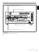
Location and Function of Parts
Chapter 1 Overview
connector on the other device before making the
connection to this unit.
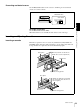
b SDI (Serial Digital Interface) IN (input) and active
through output connectors (BNC type) (optional
DSBK-1801 SDI/AES/EBU Input/Output Board
required)
Input digital video and audio signals in SDI format to the
left-hand connector. The right-hand connector is for an
active-through connection.
c SDI (Serial Digital Interface) OUT connectors
(BNC type) (optional DSBK-1801 SDI/AES/EBU
Input/Output Board required)
Output SDI-format digital video and audio signals. The
same signals are output from both connectors.
d DIGITAL AUDIO (AES/EBU) IN connectors
(BNC type) (optional DSBK-1801 SDI/AES/EBU
Input/Output Board required)
Input digital audio signals in AES/EBU format to these
connectors.
The left-hand connector (CH-1/2) is for audio channels 1
and 2, and the right-hand connector (CH-3/4) is for audio
channels 3 and 4.
e DIGITAL AUDIO (AES/EBU) OUT connectors
(BNC type) (optional DSBK-1801 SDI/AES/EBU
Input/Output Board required)
These connectors output digital audio signals in AES/EBU
format.
The left-hand connector (CH-1/2) is for audio channels 1
and 2, and the right-hand connector (CH-3/4) is for audio
channels 3 and 4.
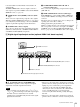
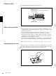
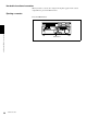
C Analog audio signal input/output section
a AUDIO IN LEVEL/600 Ω switches
Set these switches for each channel as shown in the
following table, according to the audio input levels to the
AUDIO IN CH-1 to CH-4 connectors and the required
impedance.
a) Selectable on DSR-1800AP only
b AUDIO IN CH-1 (channel 1) to CH-4 connectors
(XLR 3-pin, female)
Use these connectors to connect separate channels of
analog audio input from a player VCR or other external
audio equipment.
You can switch the audio input level setting with the
LEVEL SELECT menu item (see page 71).
c AUDIO OUT CH-1 (channel 1) to CH-4 connectors
(XLR 3-pin, male)
These connectors output channel-1 to channel-4 analog
audio signals, respectively.
It is possible to use the AUDIO OUT CH-3 and AUDIO
OUT CH-4 connectors for audio monitor output for
channels 1 and 2, respectively (use the OUTPUT CH3/4
menu item (see page 71)).
d AUDIO MONITOR OUT connector (RCA phono
jack)
This connector outputs audio signals for monitoring. The
audio signals to be output from this connector can be
MONITOR OUT
AUDIO
LEVEL
AUDIO IN AUDIO OUT
CH-1
HIGH
LOW
OFF
CH-2 CH-3
CH-4
ON
600
Ω
LEVEL
HIGH
LOW
OFF
ON
600
Ω
LEVEL
HIGH
LOW
OFF
ON
600
Ω
LEVEL
HIGH
LOW
OFF
ON
600
Ω
CH-1
CH-2 CH-3
CH-4
d AUDIO MONITOR OUT connector
c AUDIO OUT CH-1 to CH-4 connectors
a AUDIO IN LEVEL/600 Ω switches
b AUDIO IN CH-1 to CH-4 connectors
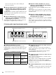
Settings of the AUDIO IN LEVEL/600 Ω switches
Audio input Switch setting
Level Impedance
−60 dBu
(microphone input)
High impedance
(about 20 k
Ω)
LOW-OFF
(left position)
+4/0/−3
a)
/−6 dBu
(line audio input)
High impedance
(about 20 k
Ω)
HIGH-OFF
(middle
position)
+4/0/−3
a)
/−6 dBm
(line audio input)
600 Ω
HIGH-ON
(right position)