
User Manual


8
Getting Started
AUDIO OUT DIGITAL OUTAUDIO IN
12
OPTICALCOAXIAL
PCM/DTS/
DOLBY DIGITAL
CONTROL S
IN
1
Y
P
B
P
R
2
1
2
MEGA
CONTROL
S-LINK
S VIDEO
OUTPUT
VIDEO
OUTPUT
COMPONENT
VIDEO OUT
L
R
L
R
S VIDEO
VIDEO
AUDIO
INPUT
L
R
S-LINK
CONTROL S
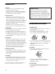
CD/DVD player
: Signal flow
TV Hookups
This connection is for listening to the sound through TV
speakers (L: left, R: right). Refer to the instructions
supplied with the component to be connected.
zYou can enjoy surround sound using your TV’s built-in
speakers
You can use 3D sound imaging to create virtual rear speakers
from the sound of built-in TV speakers without using actual rear
speakers (VES TV: Virtual Enhanced Surround TV). For details,
see page 47.
Required cords
Audio/video/S-link connecting cord (supplied) (1)
S video cord (supplied) (1)
When connecting the cords, be sure to match the color-coded
cord to the appropriate jacks on the components: Yellow (video)
to Yellow, Red (right) to Red and White (left) to White. Be sure to
make connections firmly to avoid hum and noise.
If your TV has an S-LINK (CONTROL S) connector, you can
control the CD/DVD player from the TV. Connect the TV via the
S-LINK/CONTROL S IN connector.
If your TV has an S video input connector, connect the
component via the S VIDEO OUTPUT connector using the
supplied S video cord. You will get a better picture.
Refer to the instructions supplied with the TV to be connected.
To
AUDIO
OUT
To an AC outlet
TV
To S VIDEO
OUTPUT
To
VIDEO
OUTPUT
To S VIDEO
input
To S-LINK/
CONTROL S output
Yellow
White (L)
Red (R)
Yellow
White (L)
Red (R)
To S-LINK/
CONTROL S IN
S-LINK
(CONTROL S)
S-LINK
(CONTROL S)
To audio
input
To video
input